Parts washer

a technology of parts and washers, applied in the direction of cleaning with liquids, separation processes, chemistry apparatuses and processes, etc., can solve the problem of using solvents to dirty the clean

Inactive Publication Date: 2009-06-25
CHEMCHAMP BARBADOS
View PDF4 Cites 19 Cited by
  • Summary
  • Abstract
  • Description
  • Claims
  • Application Information

AI Technical Summary

Benefits of technology

[0044]Remote monitoring of the system may be provided for service purposes. It would be a advantageous if, for example, the unit could indicate automatically over the internet or phone to a service provider when it needs service. This is better than guessing when the customer or service provider needs to set up service terms. It would streamline the whole service process and give the customer guaranteed service when needed without the customer having to call for service. Alternatively, the unit could also have a button or the like, linked remotely to the service provider, which the customer could press when service is needed.

Problems solved by technology

The disadvantage in this arrangement is that the used solvent container would need to be of a smaller volume than the clean drum so as to ensure a certain amount of overflow to ensure solvent is always available for use, thus leading to the possibility of used solvent dirtying the clean.
However, this arrangement would still be an improvement over the prior art as any overflow into the clean container would be the cleanest of the used solvent, and this would only happen if the recycler was not fast enough.
However, even if the recycler is not fast enough, the recycler would still benefit from sucking in the dirtiest used solvent from the bottom of the used solvent and it would not be sucking clean solvent being put into a separate container.

Method used


Image

  • Parts washer
  • Parts washer
  • Parts washer

Examples


Embodiment Construction

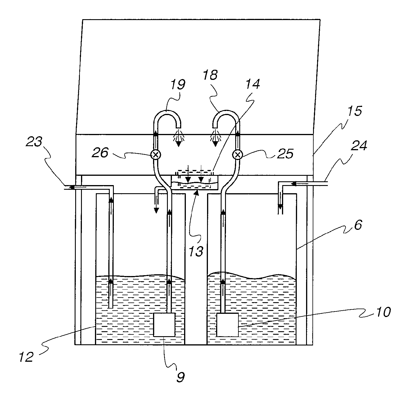
[0053]Referring to FIG. 3, the parts washer comprises a sink 15, which is provided with primary and secondary filter drains 14 and 13. For the purpose of cleaning parts placed in the sink, clean solvent is introduced through a spout 18 and used solvent is introduced through a spout 19. Clean solvent is pumped to spout 18 from a clean solvent supply drum 6 by means of a pump 10. Used solvent is pumped to spout 19 from a used solvent supply drum 12 by means of a pump 9. Contaminated solvent exits sink 15 through primary and secondary filter drains 14 and 13 and drains into drum 12. Contaminated solvent passes from drum 12 to an inlet 23 of a solvent recycler (which may be in the form of a “black box” which is separate from the parts washer) and clean solvent passes from an outlet 24 of the recycler to drum 6. The individual flows of clean and used solvent from drums 6 and 12 through the spouts 19 and 18 may be regulated by means of manually operated flow controllers 25 and 26 (hereina...


PUM


Abstract

A parts cleaner for use in a process whereby solvent is preferred to always be available and is preferred to be as clean or pure as possible for use, comprising two containers respectively for clean solvent and for capture of used solvent or a single container having separate zones for clean and used solvent, said clean container having an outlet for supplying clean solvent for cleaning. The clean container may have an outlet for supplying clean solvent for cleaning and an inlet for clean recycled solvent, the used solvent container having an inlet for used solvent, an outlet for supplying used solvent for cleaning and an outlet for supplying used solvent for recycling. The used solvent container may have an outlet for supplying used solvent for cleaning and means for automatically switching between the outlets supplying said clean solvent and said used solvent for cleaning. The clean container may have an inlet for clean recycled solvent, the used solvent container having an inlet for used solvent, an outlet for supplying used solvent for cleaning and an outlet for supplying used solvent for recycling, the parts cleaner being adapted to draw first from the clean solvent container and drain into a separate used solvent container and when clean solvent is not available, to draw from the used solvent container, thus ensuring availability of solvent at all times. Also disclosed is a solvent recycler having a distillation chamber and a filling system for the distillation chamber or a distillation zone of the distillation chamber without the use of valves when filling the distillation chamber from a used solvent zone or a container for a batch or continuous system.

Description

[0001]This application claims priority from U.S. provisional application Ser. No. 60 / 986,797 filed Nov. 9, 2007.FIELD OF THE INVENTION[0002]The present invention relates to a fluid management and recycling system which may be used as a parts washer for use in automotive, industrial and institutional facilities and similar establishments where parts are cleaned by application of solvent.BACKGROUND OF THE INVENTION[0003]Typically, a parts washer has a sink that has a hose to draw solvent from a drum for cleaning the part. The used solvent drains back into the same drum. The system is set up this way to ensure solvent is always available for use. However, the problem is that used solvent from cleaning the part draining into the clean solvent dirties the solvent in the drum, and thus the cleaning of the next part will be with dirty solvent, making it more labor intensive. The solvent becomes dirtier and dirtier with each use, increasing the required labor more and more with each use. Th...

Claims


Application Information

Patent Timeline
Patent Type & Authority Applications(United States)
IPC IPC(8): B08B3/04B08B3/08B01D3/00
CPCB08B3/14B08B3/006
Inventor MOUNT, DENNISFREDETTE, MATHIEU
Owner CHEMCHAMP BARBADOS
Why Eureka
Try Eureka