
Dividing wall distillation column control apparatus

a control apparatus and distillation column technology, applied in distillation, separation processes, evaporation, etc., can solve the problems of reducing both dehydrogenation selectivity and alkylation selectivity, affecting the efficiency of distillation, and affecting the quality of distillation

Inactive Publication Date: 2007-09-11
UOP LLC
View PDF21 Cites 103 Cited by
  • Summary
  • Abstract
  • Description
  • Claims
  • Application Information

AI Technical Summary

Benefits of technology

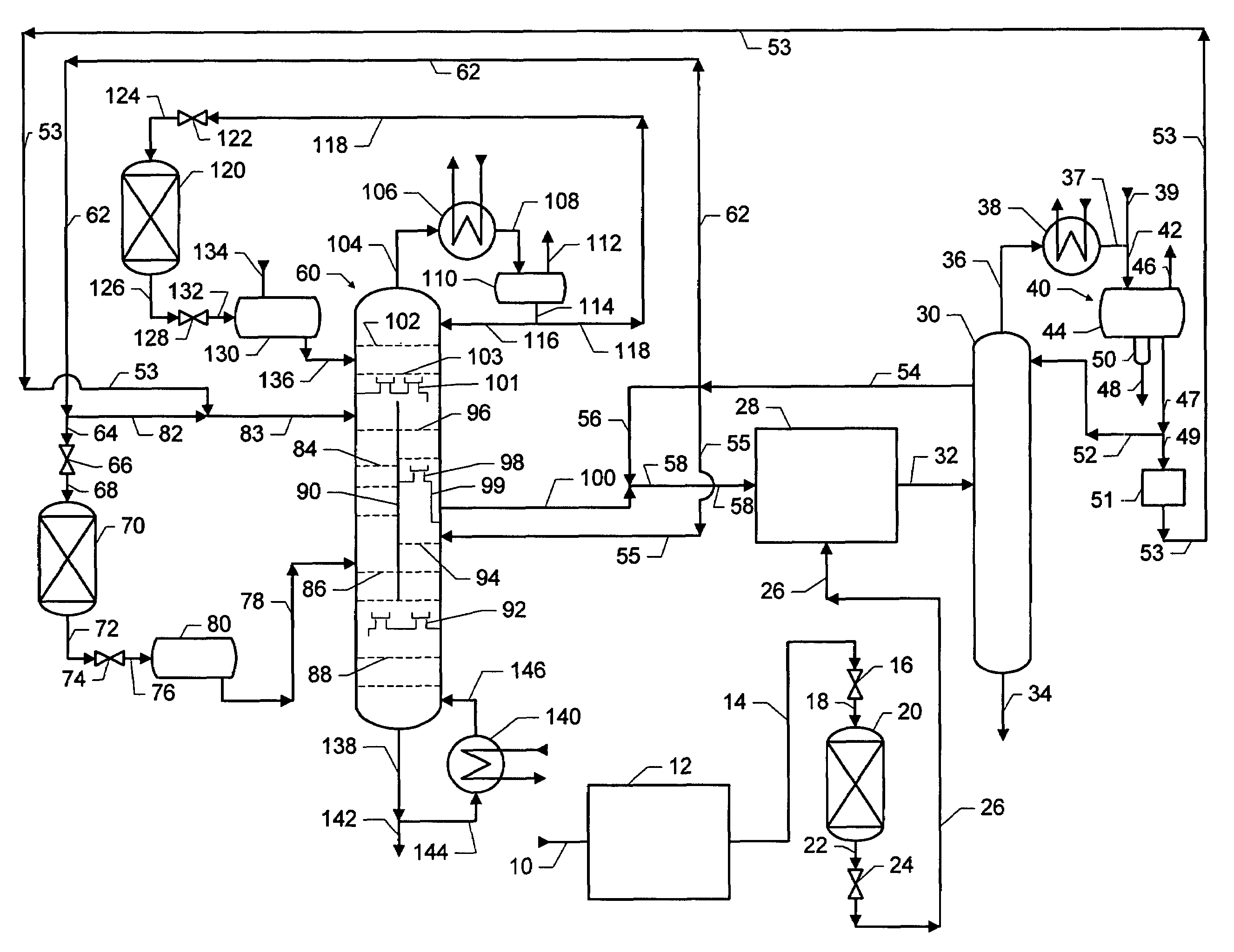
[0017]This invention is applicable to a process for the production of alkylaromatic hydrocarbons by alkylating feed aromatic hydrocarbons with olefinic hydrocarbons. More specifically, this invention is applicable to a process where both olefinic hydrocarbons and aromatic byproducts are produced by dehydrogenating paraffinic hydrocarbons, and where the aromatic byproducts are removed using a aromatic byproducts removal zone and either a dividing wall distillation column or two thermally coupled distillation columns. It has now been recognized that this invention permits the use of two thermally coupled distillation columns or of a dividing wall distillation column to reject the arom...

Problems solved by technology

Some aromatic byproducts may be more detrimental than others in deactivating solid alkylation catalysts.
It is also believed that aromatic byproducts having multiple aromatic rings are more detrimental to solid alkylation catalysts than aromatic byproducts having single aromatic rings.
Thus, using conventional distillation, the aromatic byproducts are difficult to separate from a mixture such as the dehydrogenation effluent which also contains these paraffins and olefins.
Each mole of heavy alkylate formed by this route represents the loss of two moles of feed paraffinic compound toward the production of a less-valuable product and reduces both dehydrogenation selectivity and alkylation selectivity.
Third, some of the aromatic byproducts pass through the selective alkylation zone unreacted, are recovered with the overhead liquid stream of the paraffin column which is recycled to the dehydrogenation zone, and ultimately accumulate to unacceptable concentrations.
In the prior art processes employing a solid alkylation catalyst, the concentration of aromatic byproducts in the stripping effluent stream can typically accumulate to 4–10 weight percent, which leads to rapid deactivation of solid alkylation catalyst.
This process also has a high capital cost because two columns are needed.
Despite the advantages of the dividing wall column and despite much research and study, the processing industry has long felt reluctant to use dividing wall columns in commercial processes.
This widespread reluctance has been attributed to various concerns, including control problems, operational problems, complexity, simulation difficulties, and lack of design experience.
Nevertheless, the literature documents relatively few practical uses of dividing wall columns in commercial plants.
In particular, a dividing wall distillation column has not been used for separating the effluent streams from a sorptive separation step in an alkylaromatic process.
This combination compounds the problems, difficulties, and complexity of using a dividing wall distillation column or two thermally coupled distillation columns.

Method used


Image

  • Dividing wall distillation column control apparatus
  • Dividing wall distillation column control apparatus
  • Dividing wall distillation column control apparatus

Examples


example 1

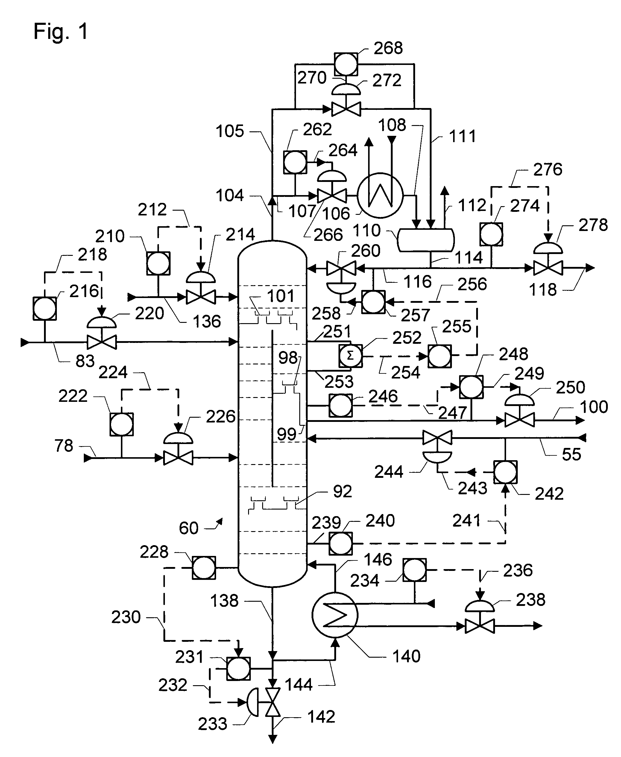
[0136]Example 1 illustrates an embodiment of the invention where the temperature controller 255 is tuned relatively more aggressively. In this example, temperature controller 255 causes a relatively large amplitude and a relatively short period in the cyclical variation in the flow of reflux in conduit 116, a relatively large range of temperatures at plate #14 in excess of the temperature set point of controller 255, and a relatively high peak and a relatively short period in the cyclical variation in the flow of n-pentane in conduit 100. The combined effect of this relatively more aggressive tuning of temperature controller 255 is a relatively high average flow rate of n-pentane in conduit 100. See the Table.

example 2

[0137]Example 2 illustrates an embodiment of the invention where the temperature controller 255 is tuned relatively less aggressively than in Example 1. In this example, temperature controller 255 causes a relatively small amplitude and a relatively long period in the cyclical variation in the flow of reflux in conduit 116, a relatively small range of temperatures at plate #14 in excess of the temperature set point of controller 255, and a relatively low peak and a relatively long period in the cyclical variation in the flow of n-pentane in conduit 100. The combined effect of this relatively less aggressive tuning of temperature is a relatively low average flow rate of n-pentane in conduit 100. See the Table. A comparison of Examples 1 and 2 shows that relatively less aggressive tuning of temperature controller 255 is preferred.

[0138]

TABLETuning of TemperatureController 255MoreLessProcess ParameterAggressiveAggressiveAmplitude of cyclical variation in flow rate296of reflux in condui...


PUM


Abstract

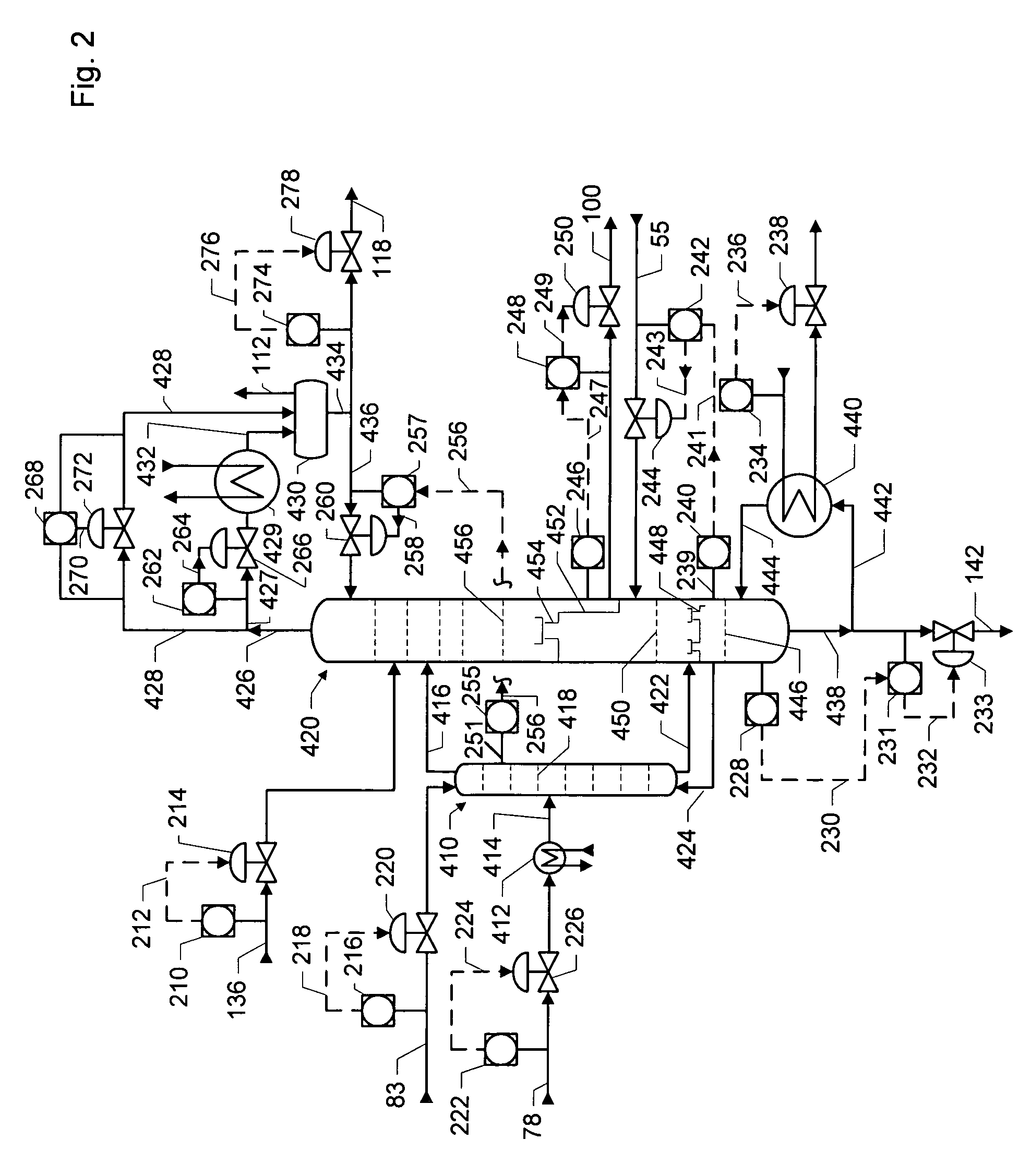
A control apparatus and control method for controlling the separation in a dividing wall distillation column of at least two feeds into at least three products is disclosed. The apparatus uses a temperature measuring device to measure the temperature of fluid in the column, a controller, and a means for adjusting the temperature of fluid in the column. The temperature measuring device may be on either side of the dividing wall or above or below the dividing wall, and more than one such device may be used. The apparatus and method may be used in the production of alkylaromatic hydrocarbons by alkylating aromatic hydrocarbons with olefinic hydrocarbons.

Description

CROSS-REFERENCE TO RELATED APPLICATION[0001]This application is a Continuation of U.S. application Ser. No. 09 / 793,250, filed on Feb. 26, 2001, now abandoned, which is incorporated herein by reference in its entirety.FIELD OF THE INVENTION[0002]This invention relates to the general field of process control as applied to distillation columns used in the petroleum, chemical, and petrochemical industries. This invention relates more specifically to a control apparatus and a control system for controlling a dividing wall distillation column used to perform the separation of two feed streams into three product streams. This invention is applicable to a process for producing alkylated aromatic compounds with removal of aromatic byproducts.BACKGROUND OF THE INVENTION[0003]Nearly forty years ago, it became apparent that household laundry detergents made of branched alkylbenzene sulfonates were gradually polluting rivers and lakes. Solution of the problem led to the manufacture of detergents...

Claims


Application Information

Patent Timeline
IPC IPC(8): B01D3/42
CPCB01D3/141B01D3/4255Y10S203/20Y10S203/19
Inventor HARRIS, JAMES W.ROSENBLUM, STEVEN P.SCHULTZ, MICHAEL A.O'BRIEN, DENNIS E.STEWART, DOUGLAS G.
Owner UOP LLC
Learn More