Plasma Cutter Having Thermal Model for Component Protection

a technology of component protection and plasma cutter, which is applied in the field of metal cutting, welding and induction heating systems, can solve the problems of affecting the performance of the system, affecting the manufacturing or assembly of the plasma cutting system, and the inability to obtain components such as motor brushes with embedded thermal sensors

Active Publication Date: 2009-06-25
ILLINOIS TOOL WORKS INC
View PDF38 Cites 32 Cited by
  • Summary
  • Abstract
  • Description
  • Claims
  • Application Information

AI Technical Summary

Benefits of technology

[0005]In one embodiment, a system is provided that includes a torch power unit. The torch power unit includes a monitor and / or control configured to determine a temperature of a component of the torch power unit based on one or more inputs without a direct temperature measurement of the component.
[0006]A method of operation is provided that includes receiving one or more inputs associated with a device and estimating a temperature of the device based on the one or more inputs without directly measuring temperature of the device.
[0007]A tangible machine-readable medium is provided that includes code for determining a thermal capacity of the device, code for determining a thermal resistance of the device, and code determining a temperature of the device based on thermal capacity and the thermal resistance.
[0008]In another embodiment, a system is provided that includes a controller configured to estimate the temperature of a device based on a thermal model and one or more feedback parameters without direct temperature measurement of the device.

Problems solved by technology

The power output and flow of the gas can affect the performance of the system.
However, addition of thermistors or other temperature sensors may complicate the manufacturing or assembly of the plasma cutting system.
Additionally, some components, such as motor brushes, are not obtainable with embedded thermal sensors.

Method used


Image

  • Plasma Cutter Having Thermal Model for Component Protection
  • Plasma Cutter Having Thermal Model for Component Protection
  • Plasma Cutter Having Thermal Model for Component Protection

Examples


Embodiment Construction

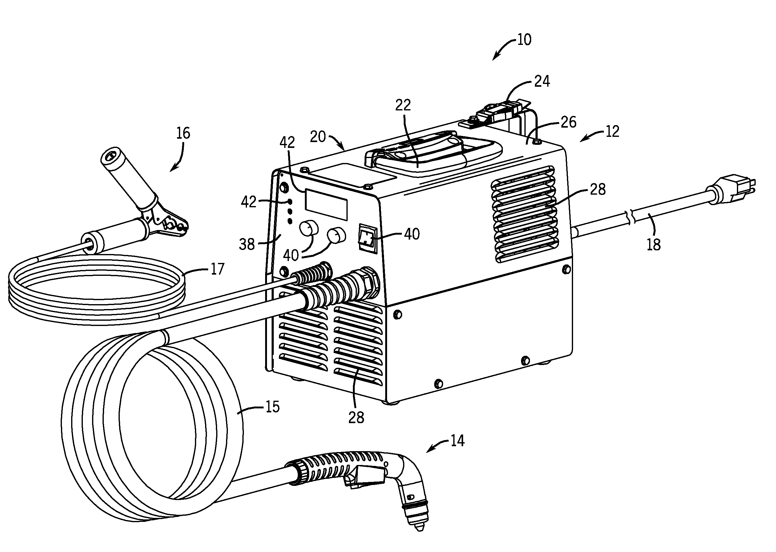
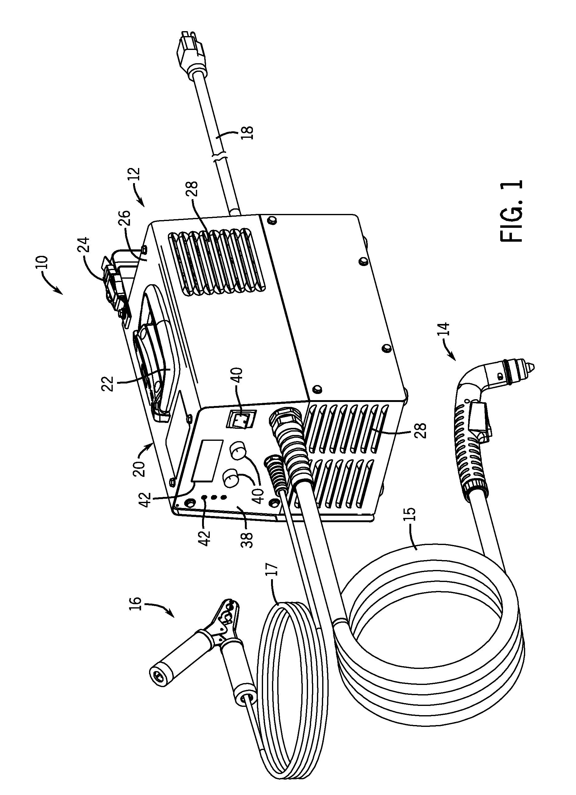
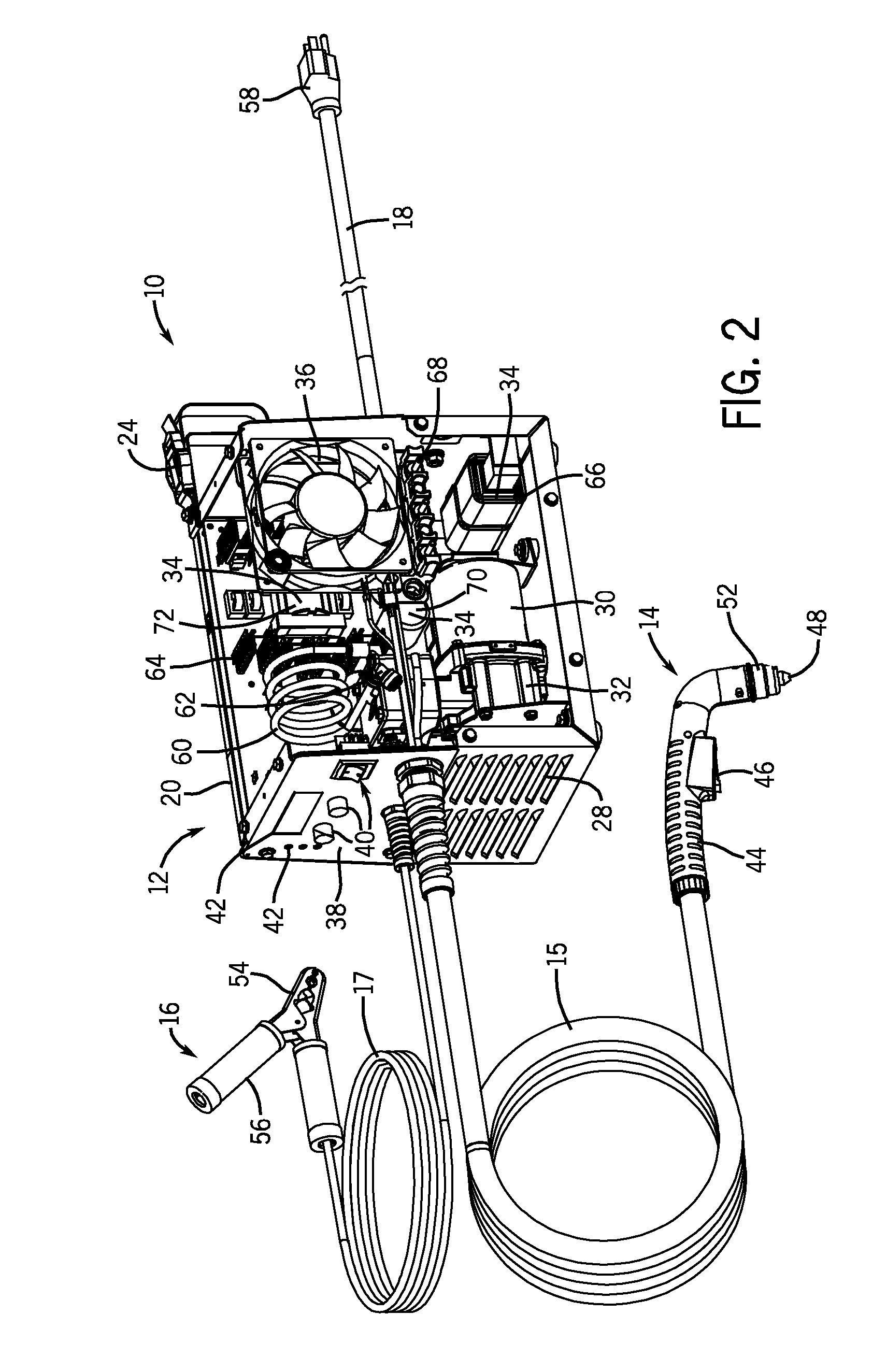
[0017]As discussed in detail below, the disclosed embodiment include a thermal monitor and control system having a thermal model for one or more components, thereby enabling thermal monitoring and control without the need for temperature sensors on the various components. In other words, the thermal model is configured to provide (e.g., estimate) the temperature of various components as a function of operating parameters other than component temperature. These operating parameters may include current, voltage, ambient temperature, and so forth. This thermal model and control system with the thermal model may be used in a variety of systems, such as electrical torch systems, compressors, generators, tools, electronics, computers, automotive, aircraft, and so forth. For purposes of illustration, the system is described below in context of plasma cutters.

[0018]Referring now to the drawings, FIGS. 1 and 2 are partial perspective views illustrating an embodiment of a portable plasma cutt...


PUM

PropertyMeasurementUnit
temperatureaaaaaaaaaa
electricalaaaaaaaaaa
magneticaaaaaaaaaa

Abstract

A system is provided that includes a torch power unit. The torch power unit includes a monitor and/or control configured to determine a temperature of a component of the torch power unit based on the one or more inputs without a direct temperature measurement of the component. A method of operation is provided that includes receiving one or more inputs associated with a device, and estimating a temperature of the device based on the one or inputs without directly measuring temperature of the device. A tangible machine-readable medium is provided that includes code for determining a thermal capacity of the device, code for determining a thermal resistance of the device, and code for determining a temperature of the device based on thermal capacity and the thermal resistance method.

Description

BACKGROUND[0001]The invention relates generally to metal cutting, welding, and induction heating systems, and more particularly to thermal protection of components in a torch power unit.[0002]A plasma cutting system creates plasma (e.g., high temperature ionized gas) to cut metal or other electrically conductive material. In general, an electrical arc converts a gas (e.g., compressed air) into plasma, which is sufficiently hot to melt the work piece while the pressure of the gas blows away the molten metal. The power output and flow of the gas can affect the performance of the system.[0003]For example, portable plasma cutting systems may include various internal components, such as transistors or other electrical devices that may be susceptible to overheating. The overheating of these components may be further aggravated by the size and compactness of portable plasma cutting systems. Because portable systems are designed with portability as a primary function, components may be clos...

Claims


Application Information

Patent Timeline
Patent Type & Authority Applications(United States)
IPC IPC(8): B23K9/00
CPCB23K10/00B23K9/1006
Inventor SALSICH, ANTHONY VAN BERGENBEISTLE, EDWARD GERARD
Owner ILLINOIS TOOL WORKS INC
Why Eureka
Try Eureka