Haptic Interface Device and Actuator Assembly Providing Linear Haptic Sensations
a technology of haptic sensation and actuator assembly, which is applied in the field of interface devices, can solve the problems of high manufacturing cost of such devices, and high cost of devices for consumers, and achieve the effect of low cost for
- Summary
- Abstract
- Description
- Claims
- Application Information
AI Technical Summary
Benefits of technology
Problems solved by technology
Method used
Image
Examples
embodiment 110
[0068]FIG. 3d is a side elevational view of a different embodiment 110 of the inertial actuator assembly 54 of FIG. 2. In this embodiment, a flexure is not used to couple the inertial mass to the actuator; instead, a rigid connection is used. An actuator 112 is grounded to the housing 50 of the interface device and includes a rotating shaft 113 that is rigidly coupled to an arm member 114. An inertial mass 116 is coupled to the housing 50 by two spring elements 117 which provide a centering, restoring force on the mass 116; the spring elements can be implemented as leaf springs, helical springs, flex joints, etc. The arm member 114 is slidably engaged with a boss 118 that is coupled to the mass 116.
[0069]When actuator shaft 113 is rotated, the arm member 114 is also rotated and causes the mass 116 to linearly move up or down along the z-axis. This linear motion is allowed by the arm member 114 sliding with respect to the boss 118 and the mass 116 as the arm member is rotated. The li...
embodiment 40
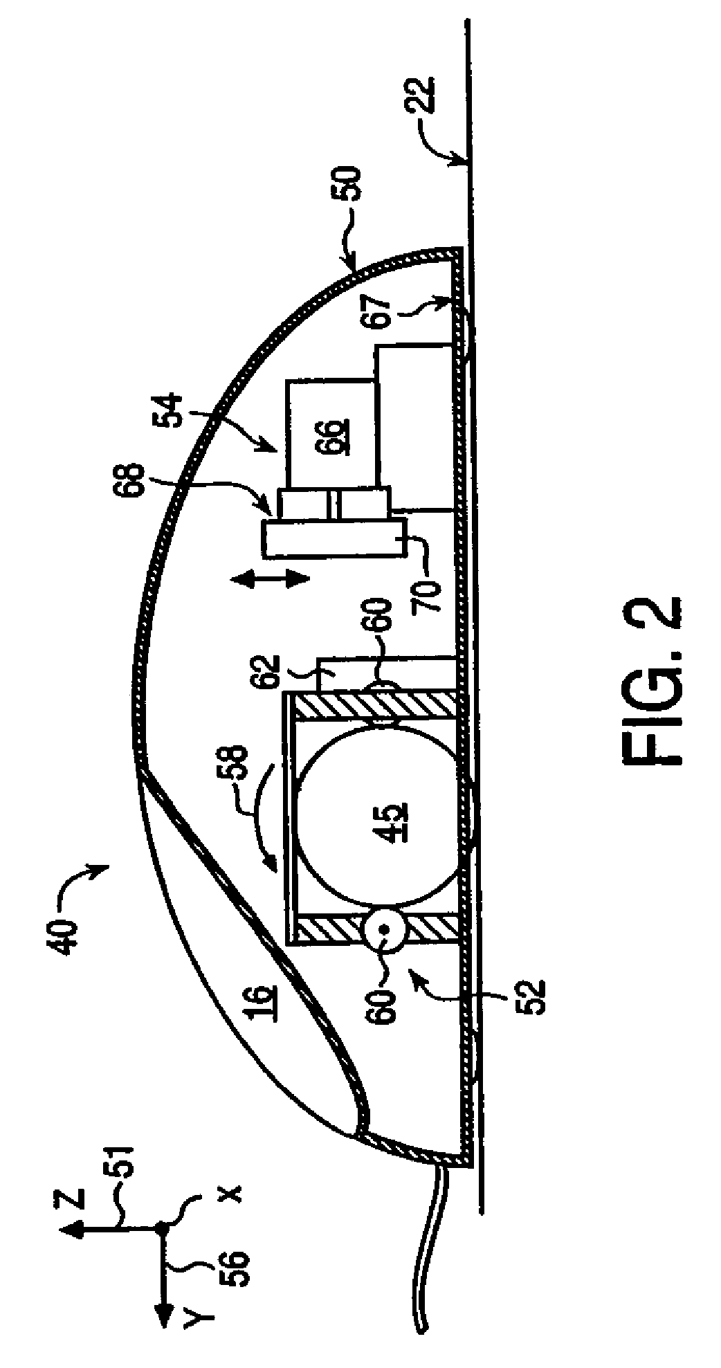
[0071]The mouse 120 includes a sensing system 52 and buttons 16 similar to those described for the mouse 40 of FIG. 2. The actuator assembly 54 includes an actuator 66, flexure 68 (such as flexure 80), and inertial mass also similar to the embodiment 40 of FIG. 2 (except that the actuator and flexure of FIG. 4 are shown rotated approximately 90 degrees with respect to FIG. 2).
[0072]Mouse 120 includes a moving cover portion 122 which can be part of the housing 50. Cover portion 122 is coupled to the base portion 124 of the housing 50 by a hinge allowing their respective motion, such as a mechanical hinge, a flexure, rubber bellows, or other type of hinge. Cover portion 122 may thus rotate about an axis B of the hinge with respect to the base portion. In other embodiments, the hinge can allow linear or sliding motion rather than rotary motion between cover and base portions. In the embodiment shown, the cover portion 122 extends in the y-direction from about the mid-point of the mouse...
embodiment 220
[0088]FIGS. 7a-7e are perspective views and FIGS. 7f and 7g are side elevational views of one flexure embodiment 220 of the actuator assembly 200 of the present invention shown in FIG. 6. In this embodiment, the mechanical transmission 205 is a unitary member, and the couplings between members of the mechanical transmission are provided as flex joints, similar to the flexible couplings provided in the embodiments of FIGS. 3 and 5.
[0089]Flexure 220 is preferably provided as a single unitary member that is coupled to a rotary actuator 202 (actuator 202 is not shown in all Figures). Flexure 220 includes a grounded portion 222 that is coupled to ground (e.g. mouse housing 50), and a moving portion 224. The moving portion 224 is flexibly connected to the grounded portion 222 at flex joints 226, 228, and 230 (not visible in all views). The moving portion 224 (best seen in FIGS. 7c and 7d) includes a rotating member 232 that is coupled to the actuator shaft via a bore 233. Rotating member ...
PUM
 Abstract
Description
Claims
Application Information
 - R&D
- Intellectual Property
- Life Sciences
- Materials
- Tech Scout
- Unparalleled Data Quality
- Higher Quality Content
- 60% Fewer Hallucinations
Browse by: Latest US Patents, China's latest patents, Technical Efficacy Thesaurus, Application Domain, Technology Topic, Popular Technical Reports.
© 2025 PatSnap. All rights reserved.Legal|Privacy policy|Modern Slavery Act Transparency Statement|Sitemap|About US| Contact US: help@patsnap.com


