Haptic interface device and actuator assembly providing linear haptic sensations

a technology of haptic sensation and actuator assembly, which is applied in the field of interface devices, can solve the problems of high manufacturing cost of such devices, and high cost of devices for consumers, and achieve the effect of low cost for

Inactive Publication Date: 2008-10-07
IMMERSION CORPORATION
View PDF256 Cites 99 Cited by
  • Summary
  • Abstract
  • Description
  • Claims
  • Application Information

AI Technical Summary

Benefits of technology

[0008]The present invention is directed toward an actuator assembly and an interface device including such an assembly that provides haptic sensations to a user. Inertial and / or contact forces are applied to a user with a low-cost actuator and mechanical structure, which allows a low-cost force feedback device to be produced.
[0014]The present invention advantageously provides a haptic feedback device that is significantly lower in cost than other types of haptic feedback devices and is thus well-suited for home consumer applications. One or more low-cost actuator assemblies of the present invention can be provided that apply a force in a particular degree of freedom, such as a Z-axis perpendicular to a support surface. A flexure is used is some embodiments to provide long-lasting and effective haptic sensations, and in some embodiments the actuator itself can be used as an inertial mass for inertial haptic sensations, saving cost and assembly time.

Problems solved by technology

One problem with current haptic feedback controllers in the home consumer market is the high manufacturing cost of such devices, which makes the devices expensive for the consumer.
A large part of this manufacturing expense is due to the inclusion of complex and multiple actuators and corresponding control electronics in the haptic feedback device.
These components are complex and require greater precision in their manufacture than many of the other components in an interface device, and thus further add to the cost of the device.
The problem with such a methodology is slow response time because the spinning mass must accelerate and decelerate over time to achieve the rotational velocity corresponding to a desired frequency output.
This can be particularly disconcerting to the user at slow frequencies and, in many embodiments, may be unsuitable for use with devices like a mouse, which also provide input in a plane that may overlap with the plane in which forces are exerted.

Method used


Image

  • Haptic interface device and actuator assembly providing linear haptic sensations
  • Haptic interface device and actuator assembly providing linear haptic sensations
  • Haptic interface device and actuator assembly providing linear haptic sensations

Examples


embodiment 110

[0068]FIG. 3d is a side elevational view of a different embodiment 110 of the inertial actuator assembly 54 of FIG. 2. In this embodiment, a flexure is not used to couple the inertial mass to the actuator; instead, a rigid connection is used. An actuator 112 is grounded to the housing 50 of the interface device and includes a rotating shaft 113 that is rigidly coupled to an arm member 114. An inertial mass 116 is coupled to the housing 50 by two spring elements 117 which provide a centering, restoring force on the mass 116; the spring elements can be implemented as leaf springs, helical springs, flex joints, etc. The arm member 114 is slidably engaged with a boss 118 that is coupled to the mass 116.

[0069]When actuator shaft 113 is rotated, the arm member 114 is also rotated and causes the mass 116 to linearly move up or down along the z-axis. This linear motion is allowed by the arm member 114 sliding with respect to the boss 118 and the mass 116 as the arm member is rotated. The li...

embodiment 40

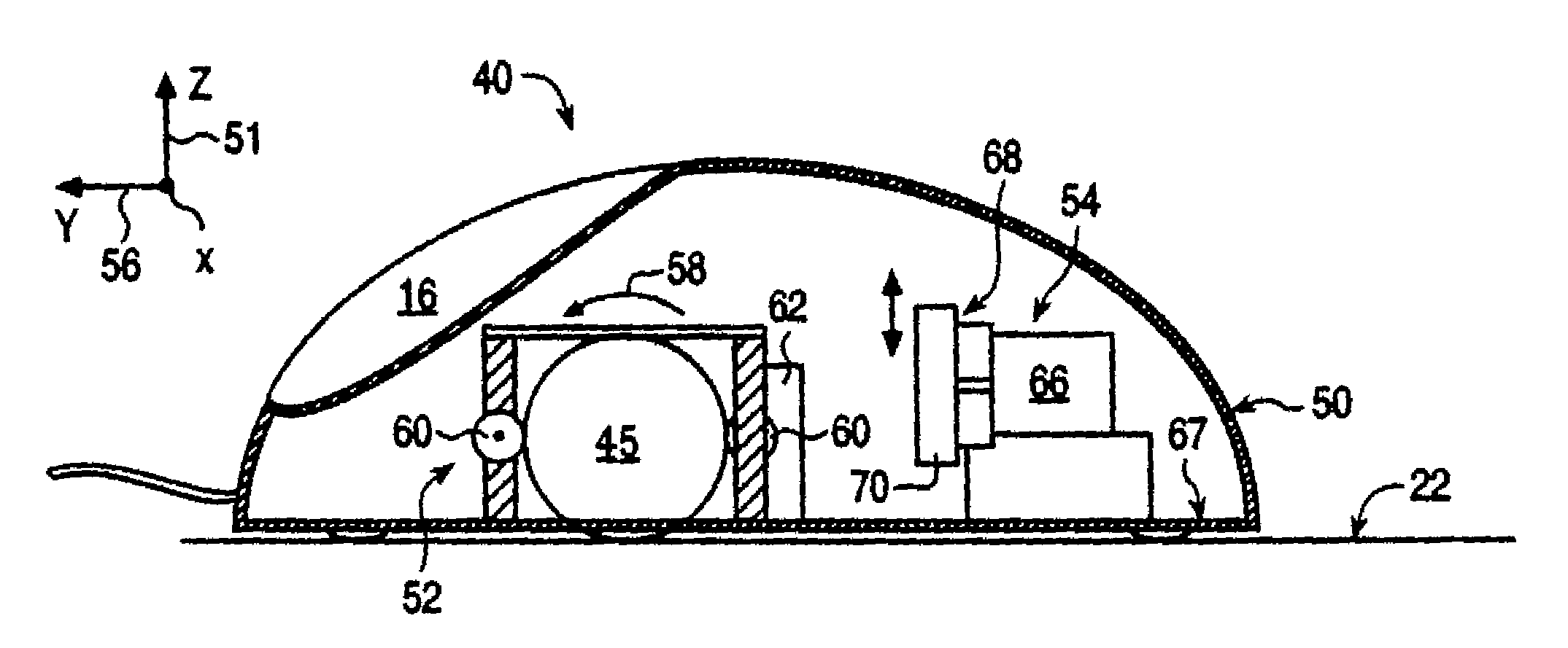
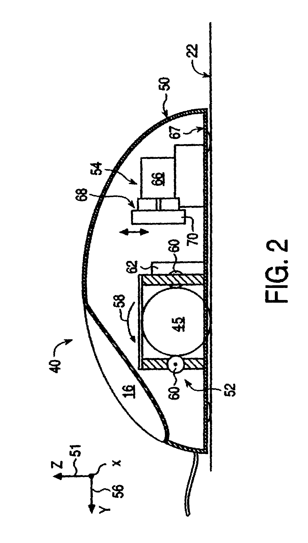
[0071]The mouse 120 includes a sensing system 52 and buttons 16 similar to those described for the mouse 40 of FIG. 2. The actuator assembly 54 includes an actuator 66, flexure 68 (such as flexure 80), and inertial mass also similar to the embodiment 40 of FIG. 2 (except that the actuator and flexure of FIG. 4 are shown rotated approximately 90 degrees with respect to FIG. 2).

[0072]Mouse 120 includes a moving cover portion 122 which can be part of the housing 50. Cover portion 122 is coupled to the base portion 124 of the housing 50 by a hinge allowing their respective motion, such as a mechanical hinge, a flexure, rubber bellows, or other type of hinge. Cover portion 122 may thus rotate about an axis B of the hinge with respect to the base portion. In other embodiments, the hinge can allow linear or sliding motion rather than rotary motion between cover and base portions. In the embodiment shown, the cover portion 122 extends in the y-direction from about the mid-point of the mouse...

embodiment 220

[0088]FIGS. 7a-7e are perspective views and FIGS. 7f and 7g are side elevational views of one flexure embodiment 220 of the actuator assembly 200 of the present invention shown in FIG. 6. In this embodiment, the mechanical transmission 205 is a unitary member, and the couplings between members of the mechanical transmission are provided as flex joints, similar to the flexible couplings provided in the embodiments of FIGS. 3 and 5.

[0089]Flexure 220 is preferably provided as a single unitary member that is coupled to a rotary actuator 202 (actuator 202 is not shown in all Figures). Flexure 220 includes a grounded portion 222 that is coupled to ground (e.g. mouse housing 50), and a moving portion 224. The moving portion 224 is flexibly connected to the grounded portion 222 at flex joints 226, 228, and 230 (not visible in all views). The moving portion 224 (best seen in FIGS. 7c and 7d) includes a rotating member 232 that is coupled to the actuator shaft via a bore 233. Rotating member ...


PUM


Abstract

An interface device and method providing haptic sensations to a user. A user physically contacts a housing of the interface device, and a sensor device detects the manipulation of the interface device by the user. An actuator assembly includes an actuator that provides output forces to the user as haptic sensations. In one embodiment, the actuator outputs a rotary force, and a flexure coupled to the actuator moves an inertial mass and / or a contact member. The flexure can be a unitary member that includes flex joints allowing a portion of the flexure to be linearly moved. The flexure can converts rotary force output by the actuator to linear motion, where the linear motion causes a force that is transmitted to the user. In another embodiment, the actuator outputs a force, and a mechanism coupling the actuator to the device housing uses the force to move the actuator with respect to the device housing. The actuator acts as an inertial mass when in motion to provide an inertial force that can be transmitted to the user. The mechanism can be a flexure including at least one flex joint or a mechanism with bearings.

Description

CROSS REFERENCE TO RELATED APPLICATIONS[0001]This application is a continuation of U.S. application Ser. No. 09 / 585,741, filed Jun. 2, 2000, now U.S. Pat. No. 6,697,043, which claims the benefit of U.S. Provisional Application No. 60 / 172,953, filed Dec. 21, 1999, entitled, “Haptic Interface Device Providing Linear Tactile Sensations Using a Rotary Actuator, and U.S. Provisional Application No. 60 / 182,868, filed Feb. 16, 2000, entitled “Haptic Device with Rotary Actuator as Inertial Mass,” and U.S. Provisional Application No. 60 / 191,333, filed Mar. 22, 2000, entitled, “Actuator Flexure Module,” all of which are incorporated herein by reference in their entireties.BACKGROUND OF THE INVENTION[0002]The present invention relates generally to interface devices for allowing humans to interface with computer systems, and more particularly to low-cost computer interface devices that allow the user to provide input to computer systems and allow computer systems to provide haptic feedback to t...

Claims


Application Information

Patent Timeline
Patent Type & Authority Patents(United States)
IPC IPC(8): G09G5/08A63F13/06G06F3/00G06F3/01G06F3/033H04L29/08
CPCA63F13/06G06F3/016G06F3/0338G06F3/03543G06F3/03545G06F3/03547G06F3/0362A63F2300/1037A63F2300/1062A63F2300/8017G06F2203/013G06F2203/014G06F2203/015H04L69/329A63F13/245A63F13/285
Inventor SHAHOIAN, ERIK J.
Owner IMMERSION CORPORATION
Why Eureka
Try Eureka