Management techniques for video playback

a management technique and video technology, applied in the field of dynamic adaptation of light sources for displays, can solve the problems of reducing battery life, affecting the quality of video playback, so as to reduce the scaling of brightness values, restore contrast, and reduce contrast

Inactive Publication Date: 2009-06-25
APPLE INC
View PDF50 Cites 9 Cited by
  • Summary
  • Abstract
  • Description
  • Claims
  • Application Information

AI Technical Summary

Benefits of technology

[0013]In some embodiments of the technique, the system identifies a region in the video image in which the scaling of the brightness values results in a visual artifact associated with reduced contrast. For example, the region may include a bright region surrounded by a darker region. Then, the system may reduce the scaling of the brightness values in the region to, at least partially, restore the contrast, thereby reducing the visual artifact. Moreover, the system may spatially filter the brightness values in the video image to reduce a spatial discontinuity between the brightness values of pixels within the region and the brightness values in a remainder of the video image.

Problems solved by technology

However, battery life is an important design criterion in many electronic devices and, because the attenuation operation discards output light 112, this attenuation operation is energy inefficient, and hence can reduce battery life.
This underexposure can occur when a camera is panned during generation or encoding of the video images.
However, it is often difficult to reliably determine the brightness of video images, and thus it is difficult to determine the scaling using existing techniques.
These non-picture portions complicate the analysis of the brightness of the video images, and therefore can create problems when determining the trade-off between the brightness of the video signals and the intensity setting of the light source 110.
Moreover, these non-picture portions can also produce visual artifacts, which can degrade the overall user experience when using the electronic device.
These effects can also complicate the analysis of the brightness of the video images and / or the determination of the appropriate trade-off between the brightness of the video image and the intensity setting of the light source 110.
In some embodiments of the technique, the system identifies a region in the video image in which the scaling of the brightness values results in a visual artifact associated with reduced contrast.

Method used


Image

  • Management techniques for video playback
  • Management techniques for video playback
  • Management techniques for video playback

Examples


embodiment 700

[0059]FIG. 7A presents a block diagram illustrating an embodiment 700 of a circuit 710. This circuit receives video signals 712 (such as RGB) associated with a given video image in a sequence of video images and outputs modified video signals 716 and an intensity setting 718 of the light source for the given video image. Note that the modified video signals 716 may include scaled brightness values for at least a portion of the given video image. Moreover, in some embodiments the circuit 710 receives information associated with video images in the sequence of video images in a different format, such as YUV.

[0060]In some embodiments, the circuit 710 receives an optional brightness setting 714. For example, the brightness setting 714 may be a user-supplied brightness setting for the light source (such as 50%). In these embodiments, the intensity setting 718 may be a product of the brightness setting 714 and an intensity setting (such as a scale value) that is determined based on the hi...

embodiment 730

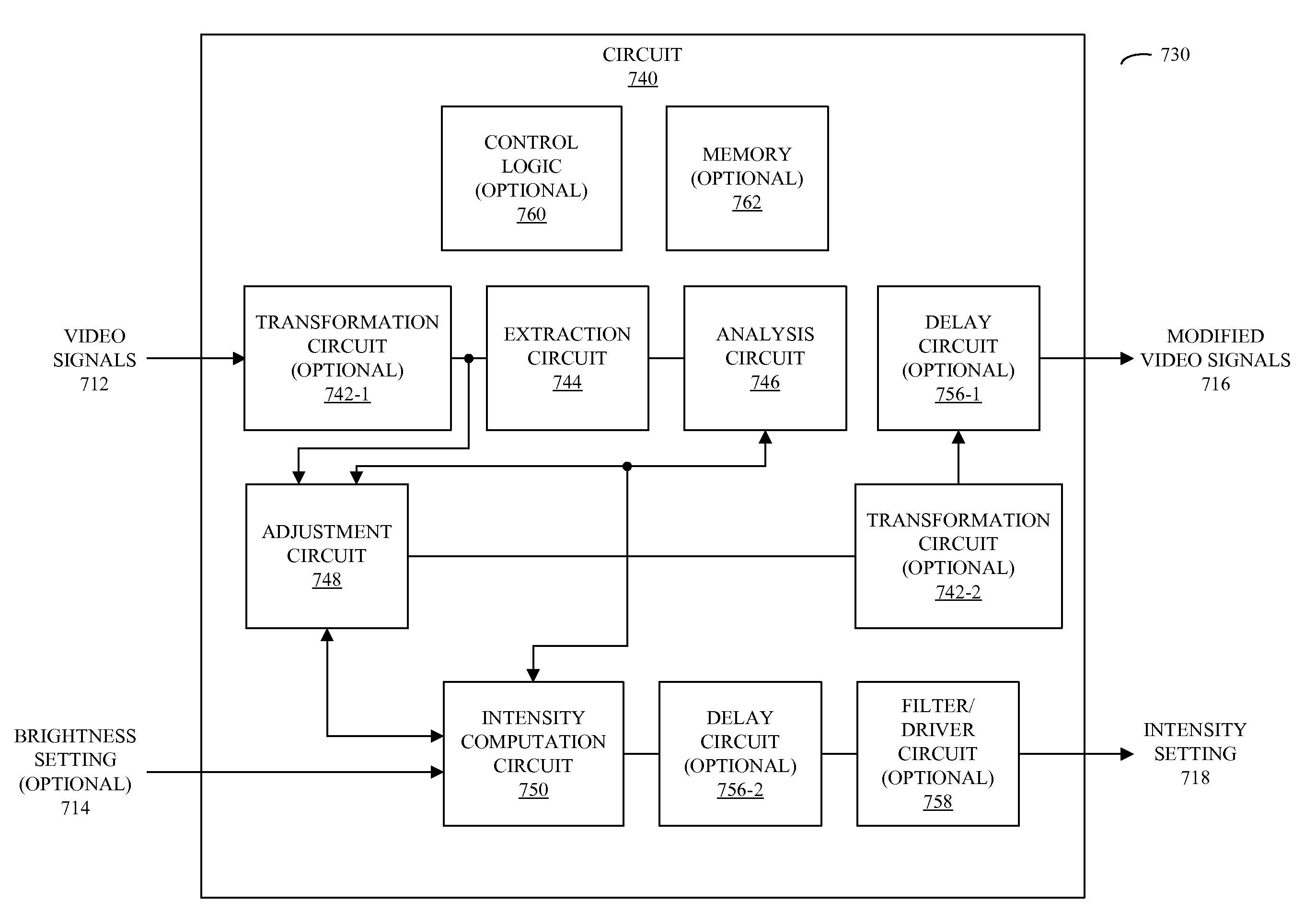
[0062]FIG. 7B presents a block diagram illustrating an embodiment 730 of a circuit 740. This circuit includes an interface (not shown) that receives the video signals 712 associated with the video image, which is electrically coupled to: optional transformation circuit 742-1, extraction circuit 744, and adjustment circuit 748. Note that the optional transformation circuit 742-1 may convert the video signals 712 to the linear brightness domain, for example, using one of the transformations 614 (FIG. 6A). Moreover, note that in some embodiments the circuit 740 optionally receives the brightness setting 714.

[0063]Extraction circuit 744 calculates one or more metrics, such as saturation values and / or a histogram of brightness values, based on at least some of the video signals, e.g., based on at least a portion of the video image. In an exemplary embodiment, the histogram is determined for the entire video image.

[0064]These one or more metrics are then analyzed by analysis circuit 746 t...


PUM


Abstract

Embodiments of a system that includes one or more integrated circuits are described. During operation, the system may determine an intensity setting of the light source based on at least a portion of a video image, such as the portion of the transformed video image that includes spatially varying visual information in the video image. Moreover, the system may modify the video image so that a product of the intensity setting and a transmittance associated with the modified video image approximately equals a product of a previous intensity setting and a transmittance associated with the video image. For example, the modification may include scaling brightness values in the transformed video image. Next, the system may identify a region in the video image in which the scaling of the brightness values results in a visual artifact associated with reduced contrast. For example, the region may include a bright region surrounded by a darker region. Then, the system may reduce the scaling of the brightness values in the region to, at least partially, restore the contrast, thereby reducing the visual artifact. Additionally, the system may spatially filter the brightness values in the video image to reduce a spatial discontinuity between the brightness values of pixels within the region and the brightness values in a remainder of the video image.

Description

CROSS REFERENCE TO RELATED APPLICATIONS [0001]This application claims priority under 35 U.S.C. 119(e) to U.S. Provisional Application Ser. No. 61 / 016,092, entitled “Management Techniques for Video Playback,” by Ulrich T. Barnhoefer, Barry J. Corlett, Victor E. Alessi, Wei H. Yao and Wei Chen, filed on Dec. 21, 2007, the contents of which are herein incorporated by reference.[0002]This application is related to: (1) pending U.S. patent application Ser. No. ______, entitled “Dynamic Backlight Adaptation for Video Images With Black Bars,” by Ulrich T. Barnhoefer, Wei H. Yao, Wei Chen and Barry J. Corlett, ______, (2) pending U.S. patent application Ser. No. ______, entitled “Dynamic Backlight Adaptation With Reduced Flicker,” by Ulrich T. Bamhoefer, Wei H. Yao, Wei Chen, Barry J. Corlett and Victor E. Alessi, ______, (3) pending U.S. patent application Ser. No. ______, entitled “Synchronizing Dynamic Backlight Adaptation,” by Ulrich T. Bamhoefer, Wei H. Yao, Wei Chen and Barry J. Corle...

Claims


Application Information

Patent Timeline
Patent Type & Authority Applications(United States)
IPC IPC(8): H04N5/14G09G5/10
CPCG09G3/3406G09G3/3611G09G2320/0247G09G2320/0271G09G2320/0646G06T5/008G09G2330/021G09G2360/16H04N5/58H04N21/44008H04N21/4402G09G2320/066
Inventor BARNHOEFER, ULRICH T.YAO, WEI H.CHEN, WEI
Owner APPLE INC
Why Eureka
Try Eureka