Pre-emphasis automatic adjusting method and data transmission system using same

a technology of automatic adjustment and data transmission system, which is applied in the direction of logic circuit coupling/interface arrangement, pulse technique, baseband system details, etc., can solve the problems of over-the-counter technology, unavoidable increase in the circuit area required on the semiconductor substrate, and large circuit scale. , to achieve the effect of simplifying the pre-emphasis adjusting circuit and reducing the time required for automatic adjustmen

Inactive Publication Date: 2009-06-25
NEC CORP
View PDF12 Cites 4 Cited by
  • Summary
  • Abstract
  • Description
  • Claims
  • Application Information

AI Technical Summary

Benefits of technology

[0013]In view of the above, it is an object of the present invention to provide a pre-emphasis automatic adjusting method which is capable of employing an eye aperture in an eye-pattern along a time axis for optimal setting of pre-emphasis strength to achieve high-speed transmission and a signal transmitting system using the method.
[0030]a transmitting circuit for transmitting the signal, which can optimally adjust pre-emphasis strength to maximize a receiving eye aperture in the receiving circuit,
[0039]a receiving circuit for receiving a signal, and a transmitting circuit for transmitting the signal, which can optimally adjust pre-emphasis strength to maximize a receiving eye aperture in the receiving circuit,
[0049]With the above configuration, a single pulse pattern is transmitted to the receiving circuit and a time length of a receiving eye aperture in the single pulse pattern in a direction of a time axis received by the receiving circuit is measured and, based on the measured time length of the eye aperture along a time axis, a pre-emphasis strength is adjusted in the transmitting circuit and, therefore, it is possible to achieve simplification of the pre-emphasis adjusting circuit. In the conventional pre-emphasis automatic adjustment by using an eye aperture (Teye) in a direction of a voltage, a process of finely changing a reference potential to detect the eye aperture and of comparing the potentials and judging the eye aperture is required, however, in the embodiments of the present invention, unlike in the conventional technology, amounts of changes and time consuming processes are not necessary, thus enabling time required for the automatic adjustment to be shortened.

Problems solved by technology

However, the above conventional technologies have problems.
This presents a problem in that a circuit scale is made to be large and an increase in a circuit area required on a semiconductor substrate is unavoidable.
Also, in the technology disclosed in the Patent Reference 4, an optical signal to noise ratio is used for optimal setting of the pre-emphasis, there are the similar problems as with the above other conventional technologies.

Method used


Image

  • Pre-emphasis automatic adjusting method and data transmission system using same
  • Pre-emphasis automatic adjusting method and data transmission system using same
  • Pre-emphasis automatic adjusting method and data transmission system using same

Examples


first embodiment

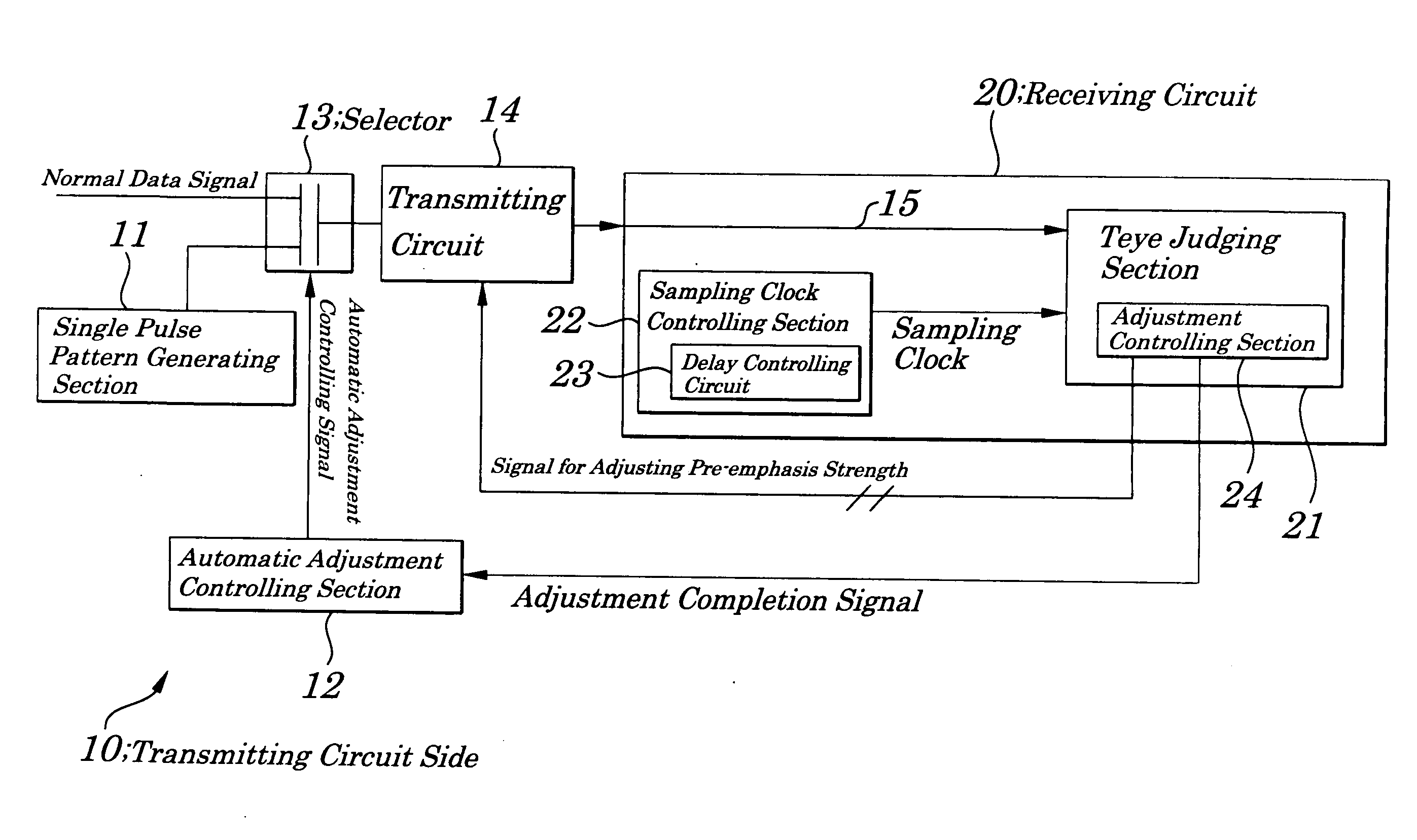
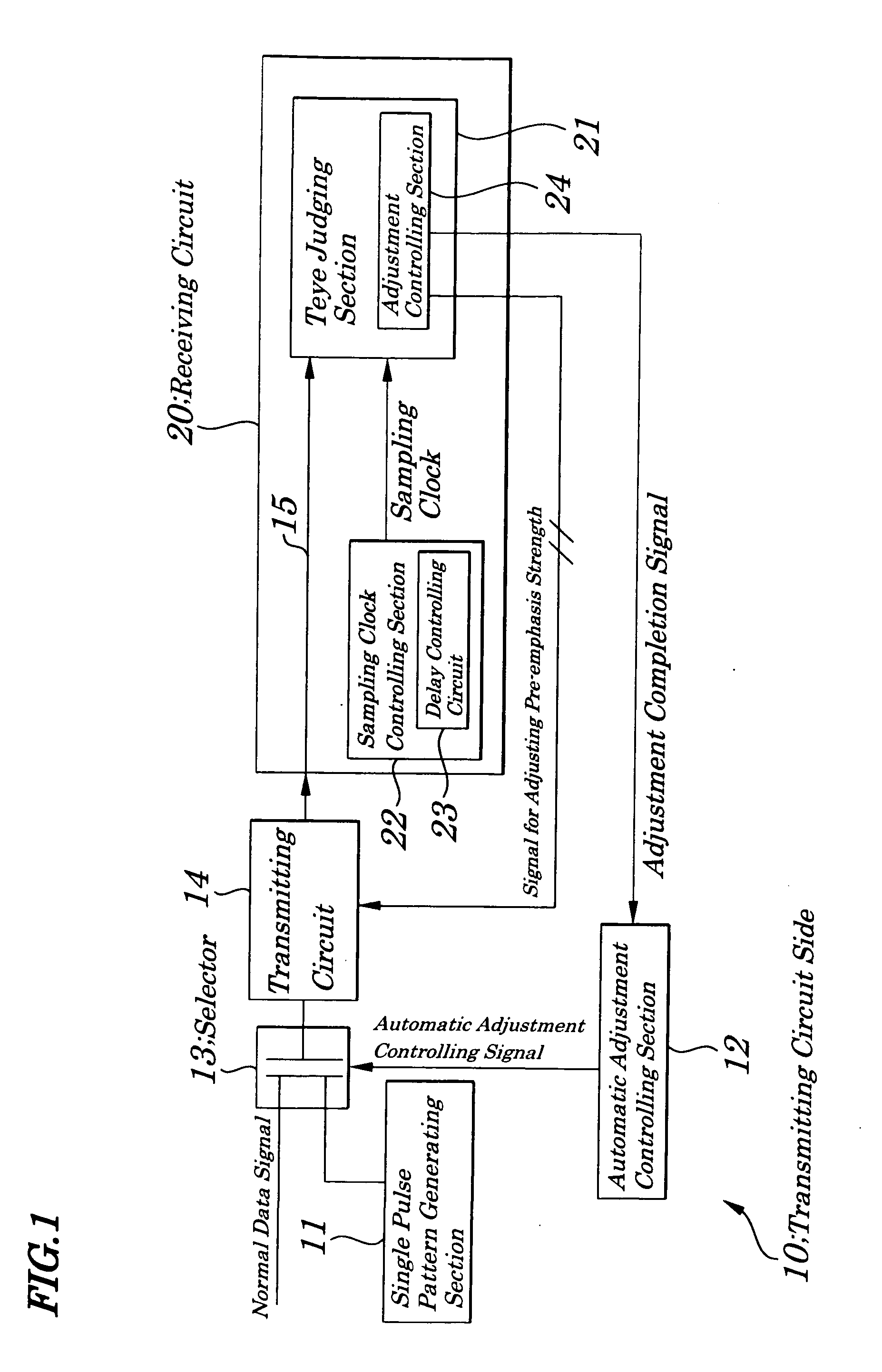
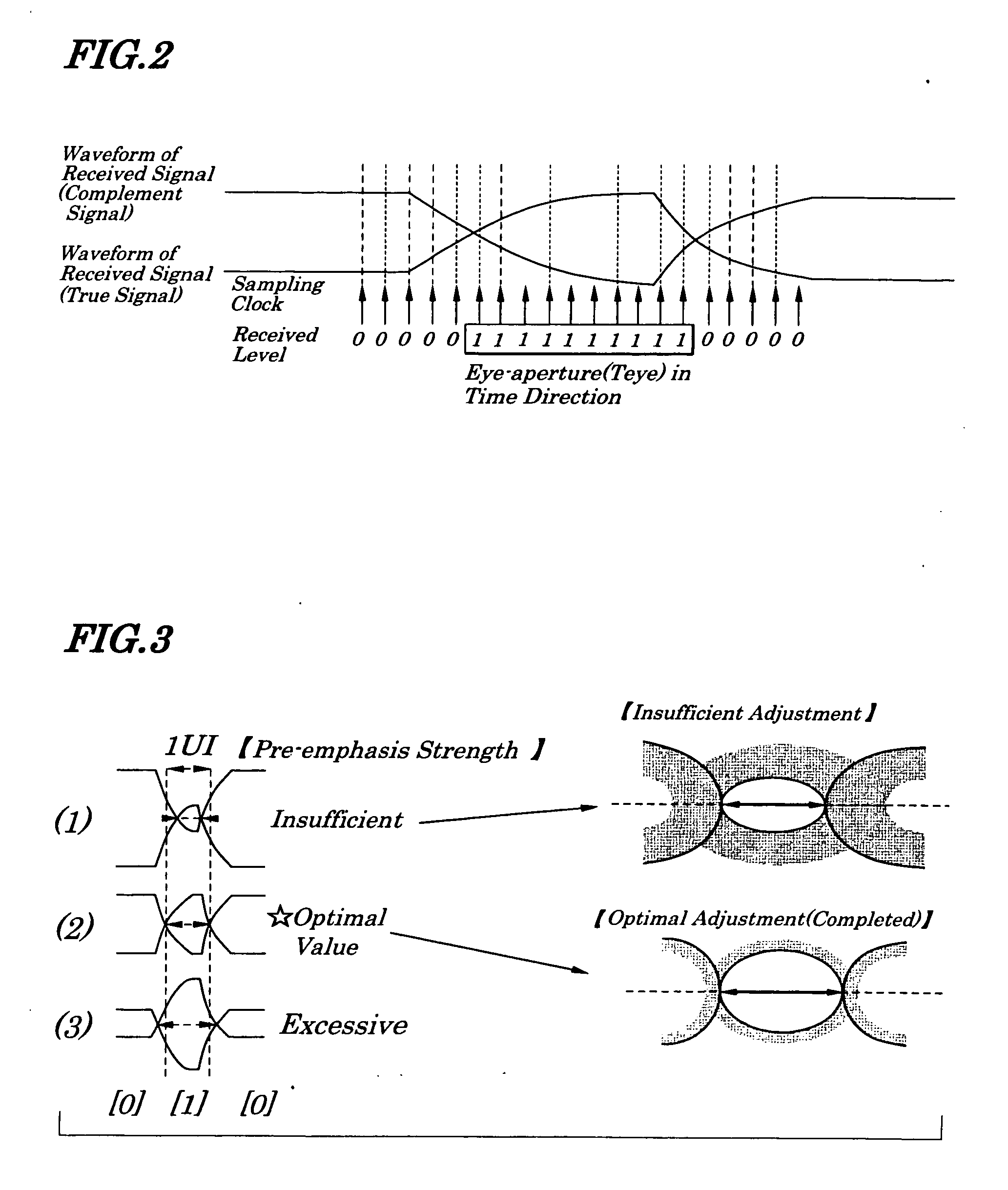
[0059]FIG. 1 is a block diagram showing electrical configurations of a signal transmission system of a first embodiment of the present invention. FIG. 2 is a diagram illustrating waveforms explaining operations of a Teye (eye aperture) judging section making up a receiving device of the signal transmission system of the first embodiment. FIG. 3 is a diagram illustrating waveforms explaining operations of an adjustment controlling section making up the signal transmission system of the first embodiment. The signal transmission system 1 of the first embodiment is a system which uses an eye aperture in a single pulse pattern in a direction of time of a received signal for setting and controlling pre-emphasis of a transmitting signal. The signal transmission system 1, as shown in FIG. 1, includes a single pulse pattern generating section 11 mounted on a transmitting circuit side 10, an automatic adjustment controlling section 12, a selector 13, a transmitting circuit 14, a Teye judging ...

second embodiment

[0067]FIG. 4 is a diagram showing electrical configurations of a signal transmission system according to a second embodiment of the present invention. Configurations of the second embodiment differ greatly from those in the first embodiment in that rough and fineness are provided to each of interval among sampling clocks. That is, the signal transmission system 1A of the second embodiment, as shown in FIG. 4, has a feature that time intervals among sampling clocks to be output from a sampling clock controlling section 22A embedding a delay control circuit 23A are configured as follows. That is, the delay controlling circuit 23A operates so that, during a time period from a specified time before a cross point where an eye waveform made up of a first signal and a second signal starts to a specified time after the cross point, short time intervals are provided and, during a time period from a specified time after the above cross point to a specified time before a cross point where the ...

third embodiment

[0072]FIG. 5 is a diagram showing electrical configurations of a signal transmission system according to the third embodiment of the present invention. Configurations of the signal transmission system of the third embodiment differ greatly from those in the first embodiment in that a single signal with a single pulse pattern is transmitted from a transmitting device to a receiving device and the received single signal with the single pulse pattern is compared with a target dc (direct current) potential to judge whether or not a signal level of the received single signal with the single pulse pattern is optimum. That is, the signal transmission system 1B of the third embodiment, as shown in FIG. 5, has a feature that a transmitting circuit 14B to transmit a pulse signal with a single pattern as a single pulse signal having a single pattern to a receiving circuit 20B is mounted on a transmitting circuit side 10B and a Teye judging section 21B to compare the single pulse signal having ...


PUM


Abstract

A signal transmission system is provided which is capable of simplifying circuits and shortening time required for automatic adjustment of pre-emphasis. A signal having a single pulse pattern is generated by a single pulse pattern generating circuit. A signal having passed through a selector is divided into two signals whose phases are inverted and which are transmitted to a receiving circuit. An eye aperture of an eye waveform in a direction of time is measured by an eye aperture judging section by using the two signals and a sampling clock output from a sampling clock controlling section. An adjustment controlling section compares the measured eye aperture with a target value for judgment and transmits the judgment result to the transmitting circuit, where pre-emphasis is adjusted based on the judgment result.

Description

CROSS REFERENCE TO RELATED APPLICATION[0001]The present application is a Continuation application of U.S. patent application Ser. No. 11 / 727,830 filed on Mar. 28, 2007.BACKGROUND OF THE INVENTION[0002]1. Field of the Invention[0003]The present invention relates to a pre-emphasis automatic adjusting method and a data transmission system and more particularly to the pre-emphasis automatic adjusting method effective for pre-emphasis for high-speed transmission and the data transmission system employing the method.[0004]The present application claims priority of Japanese Patent Application No. 2006-094866 filed on Mar. 30, 2006, which is hereby incorporated by reference.[0005]2. Description of the Related Art[0006]Conventionally, in a signal transmission system, by necessity of high-speed transmission of signals, pre-emphasis is performed on signals to be transmitted in a transmitting circuit and the signals are transmitted to a receiving circuit. In order to optically perform pre-empha...

Claims


Application Information

Patent Timeline
Patent Type & Authority Applications(United States)
IPC IPC(8): H04L27/00
CPCH04L25/03343
Inventor TANABE, MOTOI
Owner NEC CORP
Why Eureka
Try Eureka