Method and system for x-ray imaging

a technology of x-ray imaging and computed tomography, applied in the field of non-invasive imaging, can solve the problems of large detectors, inability to produce large detectors, increased mechanical stress, etc., and achieve the effect of small in-plane exten

Inactive Publication Date: 2009-06-25
GENERAL ELECTRIC CO
View PDF7 Cites 47 Cited by
  • Summary
  • Abstract
  • Description
  • Claims
  • Application Information

AI Technical Summary

Benefits of technology

[0007]The present technique provides a novel method and apparatus for providing two or more discrete X-ray emission points, i.e., focal spots, which are laterally offset, i.e., have different xy-coordinates and or longitudinally offset, i.e., have different z-coordinates. For example, the sources may be offset in an azimuthal direction such that, after rotation, each source provides a particular subset of the projection lines needed to reconstruct the imaged object within the field of view. The sources may be alternately activated, though not necessarily at equal intervals, i.e., some of the sources may be activated more frequently or for greater duration than others. One or more detectors may be employed in conjunction with the two of more sources. In one embodiment, a detector may have a relatively small in-plane extent and may be a flat-panel detector in some implementations.

Problems solved by technology

Larger detectors, however, may be undesirable for a variety of reasons.
For instance, as one might expect, larger detectors and associated acquisition electronics are both more costly and more difficult to produce.
In addition, the mechanical subsystem responsible for supporting and / or rotating a larger detector may also need to be larger and more complex and / or may be subject to greater mechanical stress.
The increased cone angle subtended by the detector longitudinal boundaries is in turn associated with increased cone-beam artifacts in the reconstructed images.
When the cone angle increases beyond a certain limit, the degradation of the image quality may become severe for axial, or step and shoot scanning.
For this reason, it may be difficult to increase the scan coverage by simply increasing the longitudinal size of the detector.

Method used


Image

  • Method and system for x-ray imaging
  • Method and system for x-ray imaging
  • Method and system for x-ray imaging

Examples


Embodiment Construction

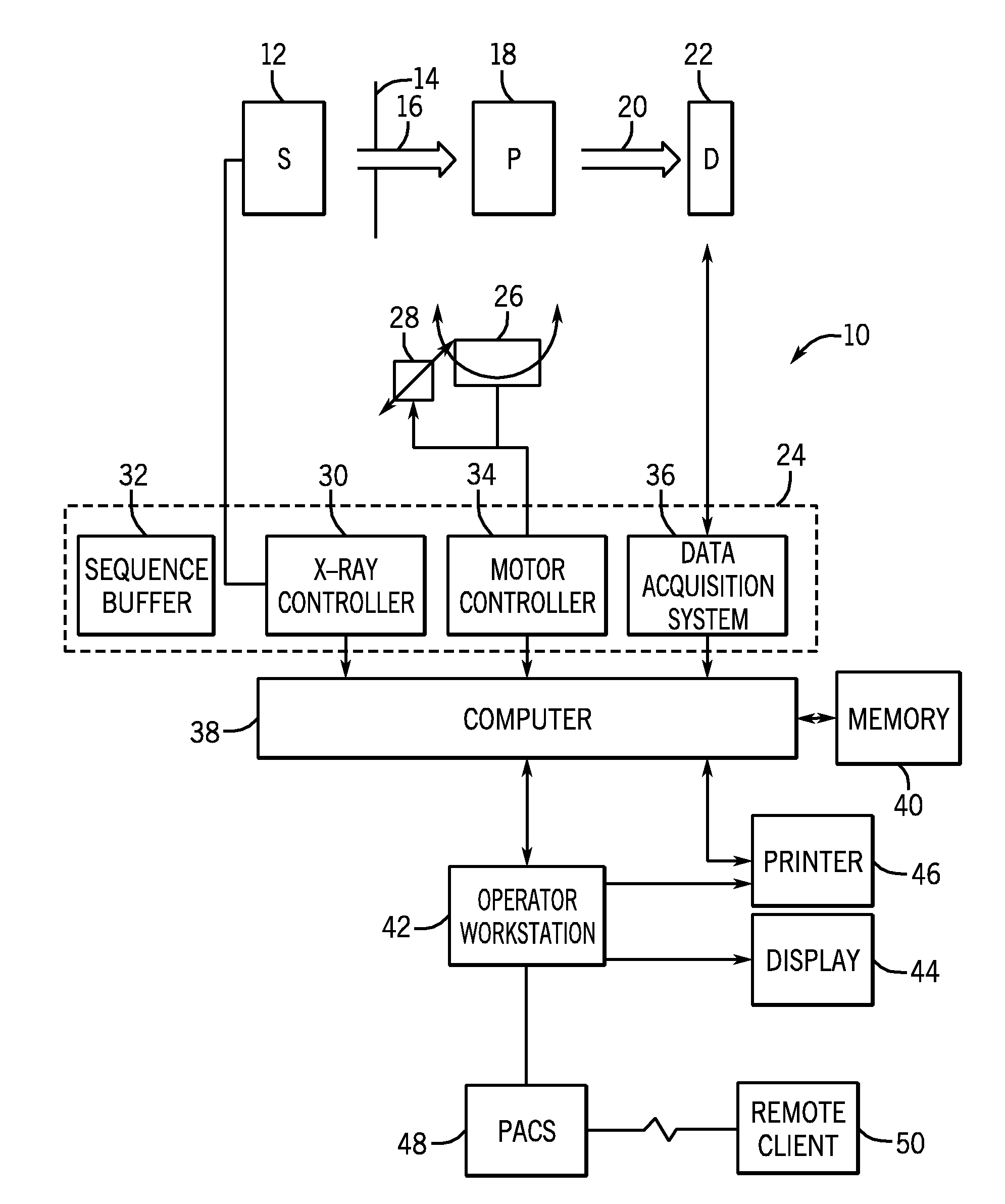
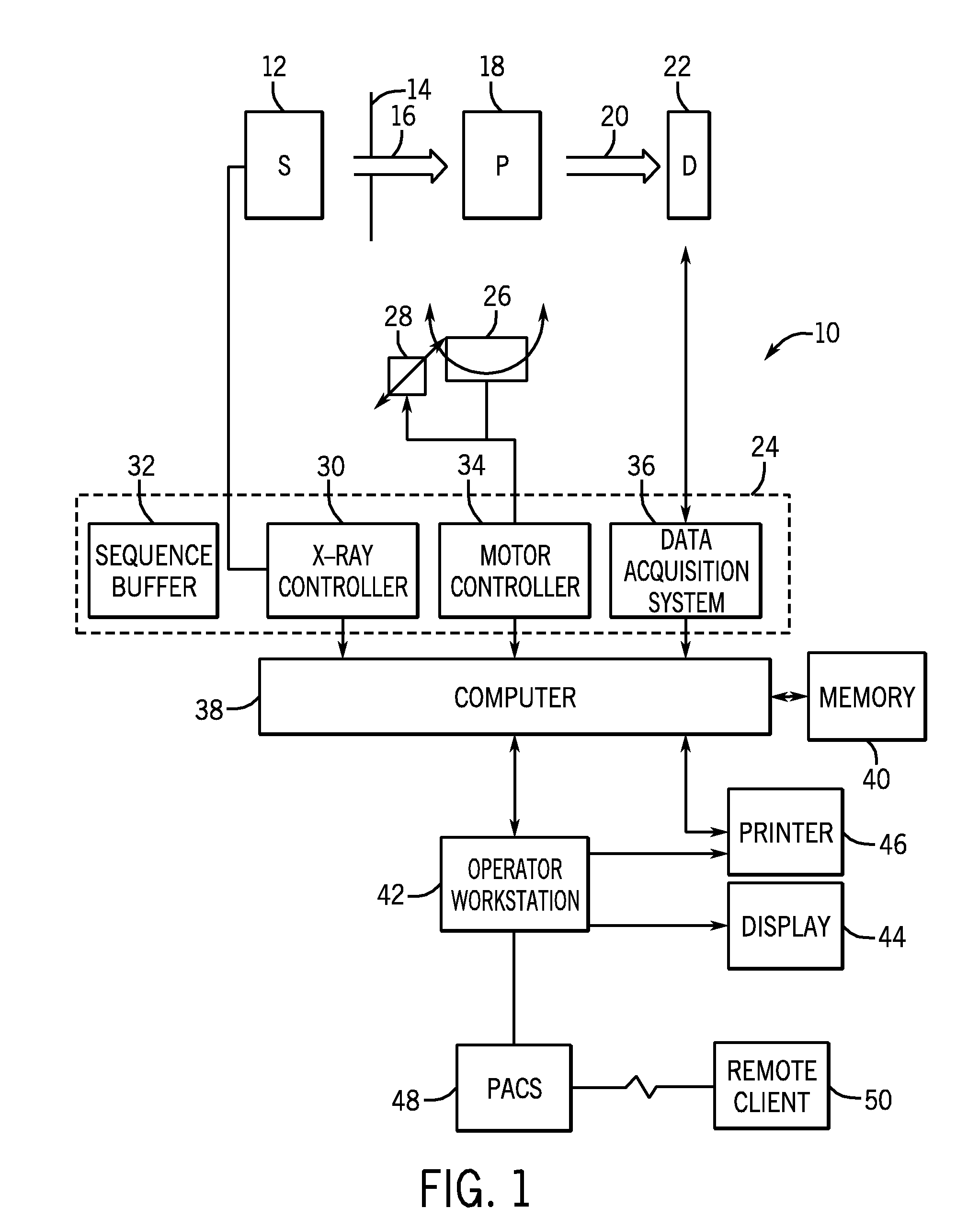
[0030]FIG. 1 illustrates diagrammatically an imaging system 10 for acquiring and processing image data. In the illustrated embodiment, system 10 is a computed tomography (CT) system designed to acquire X-ray projection data, to reconstruct the projection data into an image, and to process the image data for display and analysis in accordance with the present technique. Though the imaging system 10 is discussed in the context of medical imaging, the techniques and configurations discussed herein are applicable in other non-invasive CT imaging contexts, such as baggage or package screening and / or manufacturing quality control.

[0031]In the embodiment illustrated in FIG. 1, CT imaging system 10 includes a source 12 of X-ray radiation. As discussed in detail herein, the source 12 of X-ray radiation may consist of two or more discrete, i.e., separated, emission points or foci for X-ray emission. For example, a conventional X-ray tube may be equated with a single emission point. Alternativ...


PUM


Abstract

A technique is provided for imaging a field of view using an X-ray source comprising two or more emission points. The two or more emission points may be independently operated. Independent operation of the two or more emission points in performed in accordance with a list of commands that specifies the operation of the emission points. The list of commands, in one embodiment, is stored in a sequence buffer. In other embodiments, the list of commands is generated for a given usage, without being stored in a sequence buffer.

Description

CROSS REFERENCE TO RELATED APPLICATIONS[0001]This application is a Continuation-in-Part of U.S. patent application Ser. No. 11 / 970,403, entitled “Method and System for Imaging Using Multiple Offset X-Ray Emission Points”, filed Jan. 7, 2008, which is a continuation of U.S. patent application Ser. No. 10 / 789,539, entitled “Method and System for Imaging Using Multiple Offset X-Ray Emission Points”, filed Feb. 27, 2004, which are both herein incorporated by reference in their entirety for all purposes.STATEMENT REGARDING FEDERALLY SPONSORED RESEARCH & DEVELOPMENT[0002]This invention was made with Government support under contract number NIH18799870 awarded by the National Institute of Health. The Government has certain rights in the invention.BACKGROUND OF THE INVENTION[0003]The present disclosure relates generally to the field of non-invasive imaging and more specifically to the field of computed tomography (CT) imaging. In particular, the present disclosure relates to scanner configu...

Claims


Application Information

Patent Timeline
Patent Type & Authority Applications(United States)
IPC IPC(8): A61B6/00H05G1/70
CPCA61B6/032A61B6/4014A61B6/027A61B6/4085A61B6/4266A61B6/4028
Inventor DE MAN, BRUNO KRISTIAAN BERNARDHARRISON, DANIEL DAVIDIATROU, MARIASMYTH, BRIAN PATRICKYIN, ZHYEBASU, SAMIT KUMARSENGUPTA, SOUMASANZA, PETER CLAUDIUS
Owner GENERAL ELECTRIC CO
Why Eureka
Try Eureka