Ultrasonic diagnosis device, ultrasonic image analysis device, and ultrasonic image analysis method

a diagnostic device and ultrasonic imaging technology, applied in diagnostics, medical science, applications, etc., can solve the problems of difficult to accurately observe the “strain” of myocardial tissues at and difficult to accurately set the predetermined time phase in the method based on the end systol

Active Publication Date: 2009-06-25
TOSHIBA MEDICAL SYST CORP +1
View PDF3 Cites 17 Cited by
  • Summary
  • Abstract
  • Description
  • Claims
  • Application Information

AI Technical Summary

Benefits of technology

[0014]The invention is contrived in view of the above-mentioned problems and it is thus an object of the invention to provide an ultrasonic diagnosis device, an ultrasonic image analysis device, and an ultrasonic image analysis method that can allow parameter image data corresponding to a predetermined heartbeat time phase of the diastole effective for diagnosis to accurately and reliably be displayed at the time of observing the parameter image data based on motion parameters of myocardial tissues which can be acquired by analyzing ultrasonic image data.

Problems solved by technology

When the parameter image data at the predetermined time phase of the initial diastole are selectively observed, it was difficult to accurately observe the “strain” of the myocardial tissues at the predetermined time phase from the parameter image data continuously displayed as the moving images like the past.
Since it is necessary to use an end systole of the myocardial tissues as a reference to accurately setting the predetermined time phase, it was difficult to accurately set the predetermined time phase in the methods based on the end systole specified by R-wave timing of the electrocardiographic waveforms like the past.

Method used


Image

  • Ultrasonic diagnosis device, ultrasonic image analysis device, and ultrasonic image analysis method
  • Ultrasonic diagnosis device, ultrasonic image analysis device, and ultrasonic image analysis method
  • Ultrasonic diagnosis device, ultrasonic image analysis device, and ultrasonic image analysis method

Examples


first embodiment

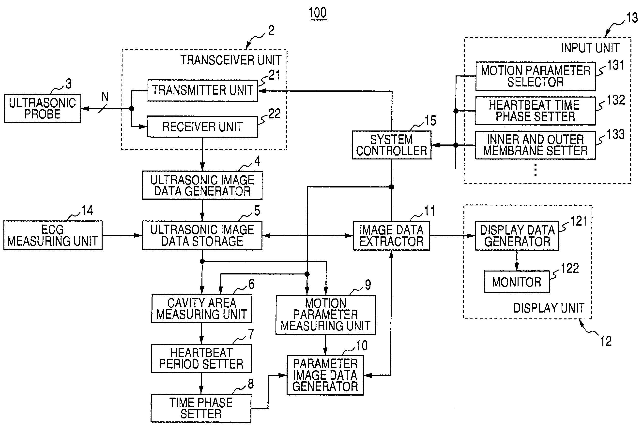
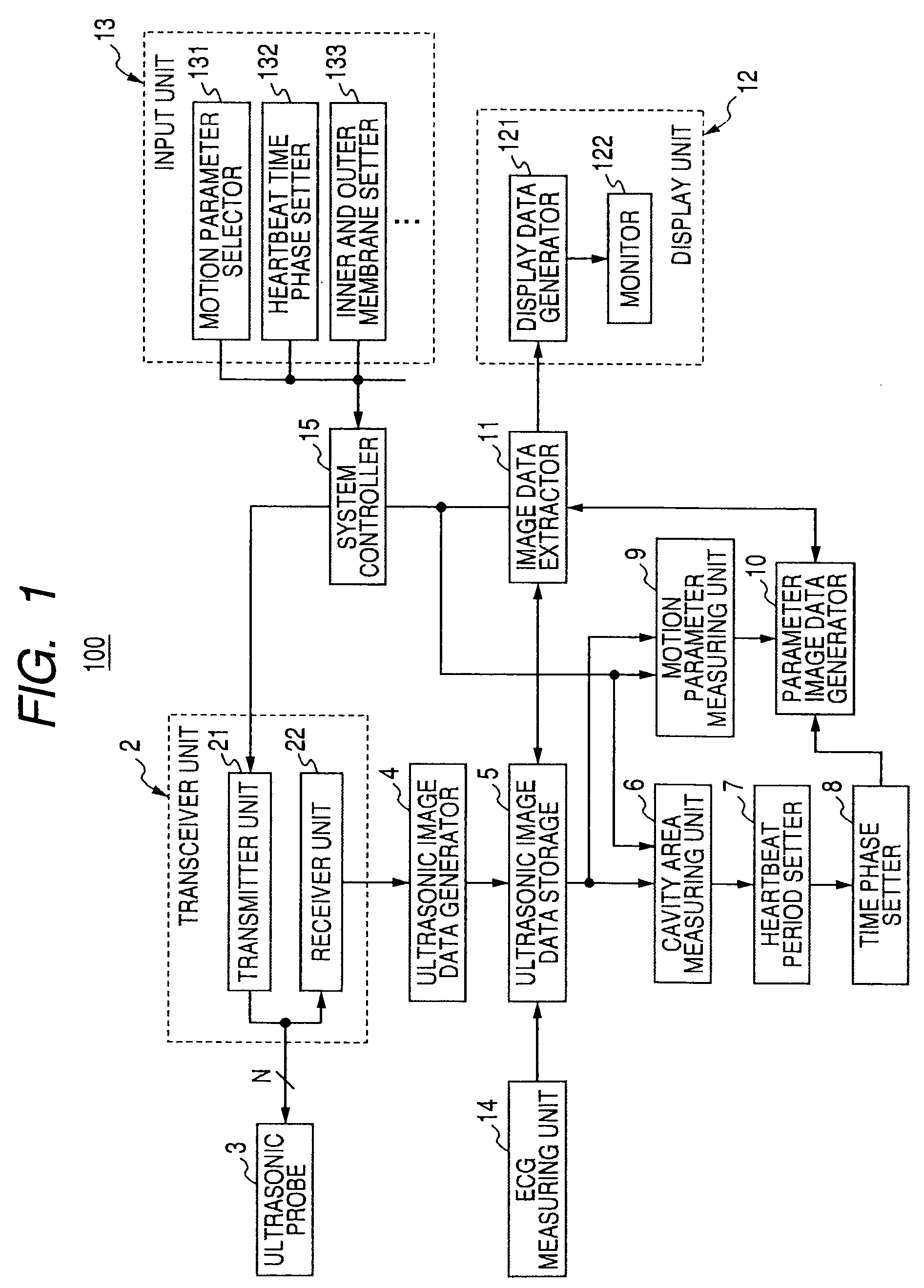
[0026]An ultrasonic diagnosis device according to a first embodiment of the invention to be described below transmits and receives ultrasonic waves to and from a sample to generate B-mode image data as ultrasonic image data and performs a tracking process on the ultrasonic image data to two-dimensionally or three-dimensionally measure a “strain” of a cardiac tissue as a motion parameter. In addition, the ultrasonic diagnosis device sets a diastolic heartbeat time phase based on the systole end on the basis of a systole end specified by a time phase where a cardiac cavity area of the ultrasonic image data is the minimum and a diastole end specified by an R wave in electrocardiographic waveforms of the sample measured at the same time as collecting the ultrasonic image data, and adds the diastolic heartbeat time phase to time-series parameter image data generated on the basis of the motion parameter of the ultrasonic image data. The ultrasonic diagnosis device extracts and displays fr...

second embodiment

[0075]A second embodiment of the invention will be described. An ultrasonic image analysis device according to the second embodiment of the invention performs a tracking process on time-series ultrasonic image data collected in advance in a state where the R-wave timing information based on the electrocardiographic waveform of a sample is added thereto and two-dimensionally measures a motion parameter of a myocardial tissue. On the other hand, the ultrasonic image analysis device sets a diastolic heartbeat time phase based on the systole end on the basis of the systole end specified by the time phase at which the cardiac cavity area of the ultrasonic image data is the minimum and the diastole end specified by the R-wave timing information added to the ultrasonic image data, and adds the diastolic heartbeat time phase to the respective time-series parameter image data generated on the basis of the motion parameter of the ultrasonic image data. The ultrasonic image analysis device ext...


PUM


Abstract

A motion parameter measuring unit two-dimensionally measures a motion parameter of a myocardial tissue by a tracking process on time-series ultrasonic image data acquired by transmission and reception of ultrasonic waves to and from a sample. On the other hand, a time phase setting unit adds a diastolic heartbeat time phase, which is set on the basis of a systole end specified by a time phase where a cardiac cavity area of the ultrasonic image data is the smallest and a diastole end specified by an R wave in an electrocardiographic waveform of the sample, relative to the systole end to time-series parameter image data generated by a parameter image data generating unit on the basis of the motion parameter. An image data extracting unit extracts parameter image data to which the diastolic heartbeat time phase closest to a desired diastolic heartbeat time phase set by an input unit is added and displays the extracted parameter image data on a display unit.

Description

CROSS-REFERENCE TO RELATED APPLICATIONS[0001]This application is based upon and claims the benefit of priority from prior Japanese Patent Applications No. 2007-329002, filed Dec. 20, 2007; and No. 2008-257511, filed Oct. 2, 2008, the entire contents of both of which are incorporated herein by reference.BACKGROUND OF THE INVENTION[0002]1. Field of the Invention[0003]The present invention relates to an ultrasonic diagnosis device, an ultrasonic image analysis device, and an ultrasonic image analysis method, and more particularly, to an ultrasonic diagnosis device, an ultrasonic image analysis device, and an ultrasonic image analysis method that can generate and display parameter image data based on motion parameters of myocardium and the like by analyzing ultrasonic image data collected from a sample.[0004]2. Description of the Related Art[0005]An ultrasonic diagnosis device radiates ultrasonic pulses generated from a vibrating element built in an ultrasonic probe into a sample, recei...

Claims


Application Information

Patent Timeline
Patent Type & Authority Applications(United States)
IPC IPC(8): A61B8/00
CPCA61B5/04012A61B8/485A61B8/0883A61B8/08A61B5/316
Inventor KAWAGISHI, TETSUYAABE, YASUHIKOOHUCHI, HIROYUKIISHII, KATSUHISA
Owner TOSHIBA MEDICAL SYST CORP
Why Eureka
Try Eureka