Locking Clip Assembly With Spring-Loaded Collar

a technology of locking clip and spring loaded collar, which is applied in the field of safety devices, can solve the problems of needle stick injury risk to medical personnel, discomfort to patients, and risk, and achieve the effect of preventing the retraction of the needl

Active Publication Date: 2009-06-25
KPR U S LLC
View PDF7 Cites 77 Cited by
  • Summary
  • Abstract
  • Description
  • Claims
  • Application Information

AI Technical Summary

Benefits of technology

[0009]A catheter assembly is disclosed which includes a cannula assembly, a locking clip assembly and a housing. The cannula assembly includes a cannula and a cannula hub. The locking clip assembly includes a locking clip, a collar, and a biasing member. The locking clip has a first leg defining a trigger hole and a second leg defining a binding hole. The collar is positioned to engage the locking clip and the biasing member is positioned to urge the collar into engagement with the locking clip to urge the locking clip from a first orientation to a second orientation. The housing defines a chamber dimensioned to receive the locking clip assembly. An insertion needle is movable from an advanced position to a retracted position, wherein in the advanced position, the insertion needle extends through the housing, the binding and trigger holes of the locking clip and the cannula assembly such that a sharp distal end of the insertion needle extends from a distal end of the cannula and the locking clip is retained in its first orientation. In the retracted position, the distal end of the insertion needle is withdrawn through the cannula assembly and the trigger hole such that the collar and biasing member urge the locking clip to the second orientation, wherein the binding hole is positioned to bind with the insertion needle to prevent retraction of the insertion needle. In one embodiment, the biasing member includes a coil spring.

Problems solved by technology

One problem associated with the use of I.V. catheters is the risk to medical personnel of needle stick injury during disposal of the needle after separation of the needle from the catheter.
Such locking clip devices, due to the increased diameter of the insertion needle, may cause discomfort to a patient.
In addition, where an annular ring is secured to the insertion needle, the risk exists that the annular ring will become detached from the insertion needle and occlude flow within a patient's vasculature.
Such a spring force applied to the insertion needle by the spring clip may create a high drag force on the insertion needle as it is separated from the catheter assembly making it difficult for a clinician to remove the insertion needle from the catheter assembly.

Method used


Image

  • Locking Clip Assembly With Spring-Loaded Collar
  • Locking Clip Assembly With Spring-Loaded Collar
  • Locking Clip Assembly With Spring-Loaded Collar

Examples


Embodiment Construction

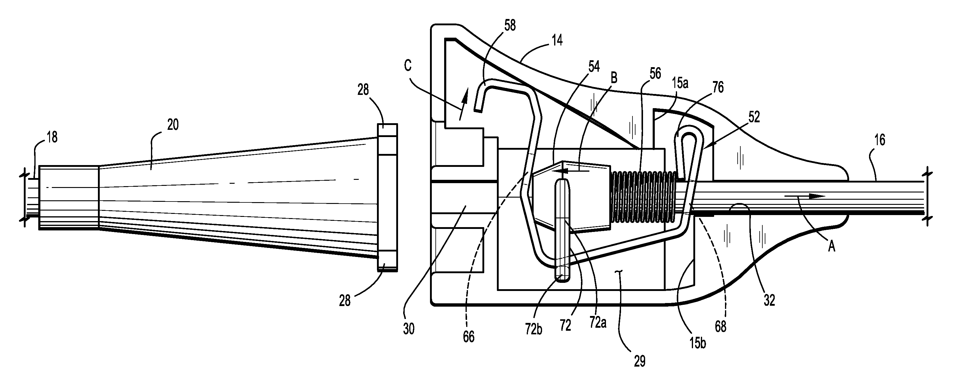
[0021]Embodiments of a catheter assembly incorporating the presently disclosed locking clip assembly with spring-loaded collar will now be described in detail wherein like numerals designate identical or corresponding elements in each of the several views. In this description, the term proximal is generally used to indicate relative nearness of a referenced item to a user of the device and the term distal is used to indicate relative remoteness of a referenced item to a user of the device.

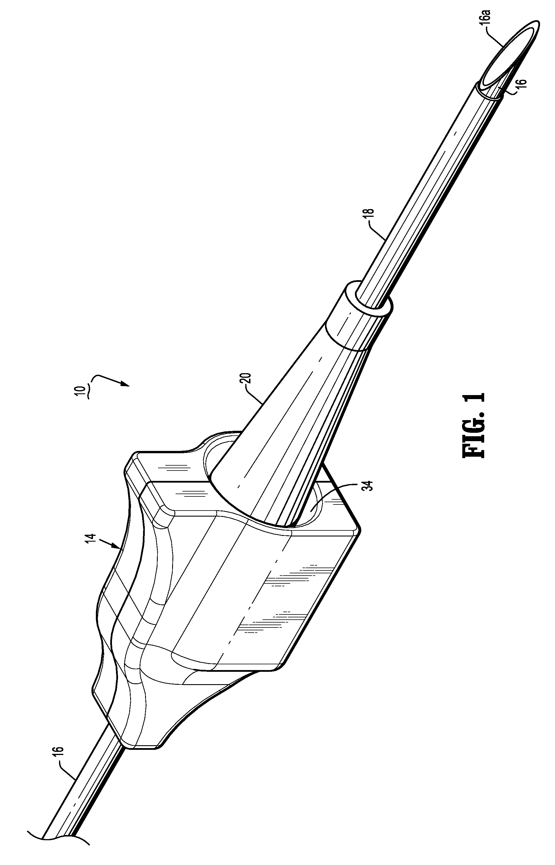
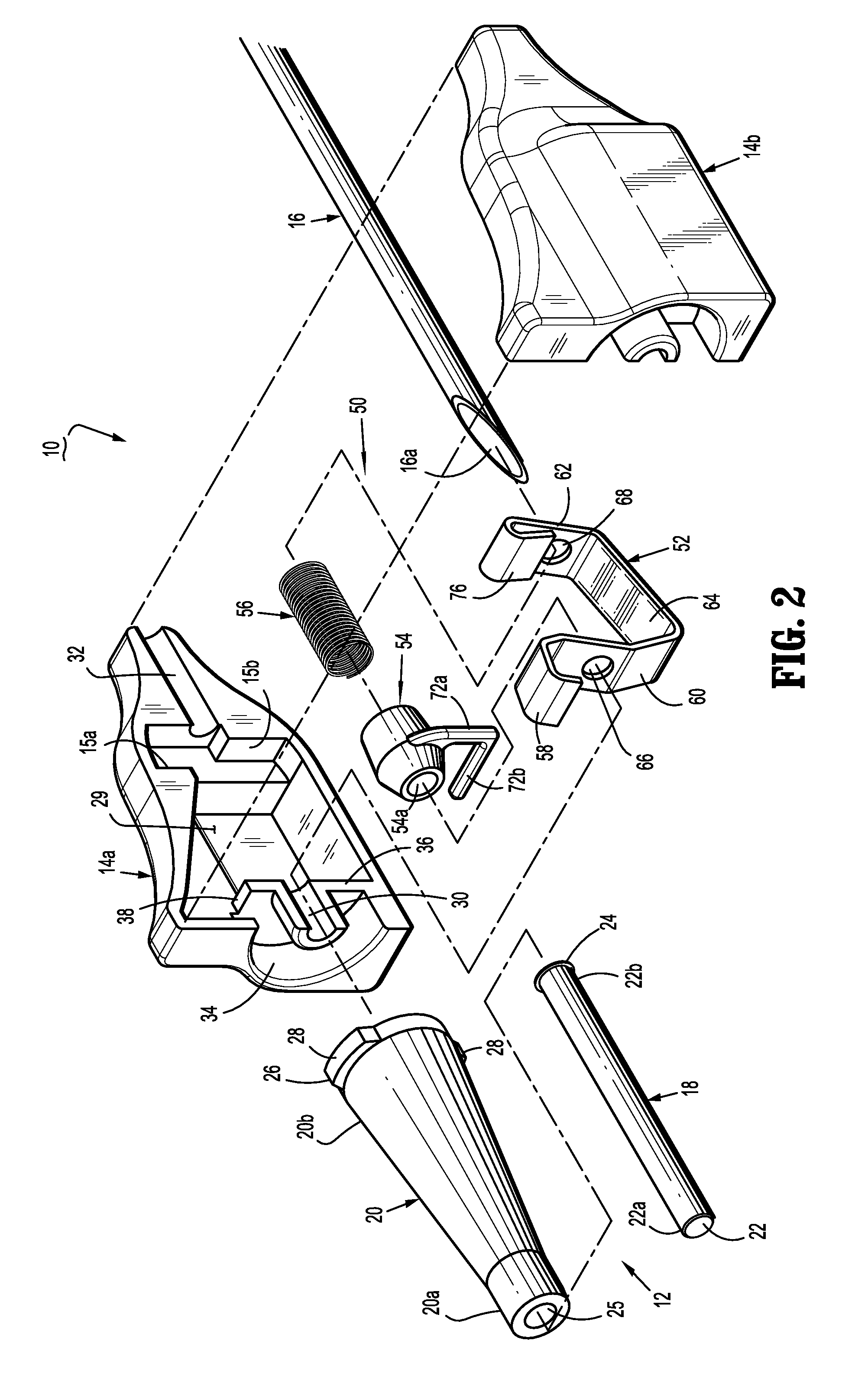
[0022]FIGS. 1-4 illustrate a catheter assembly 10 which incorporates one embodiment of the presently disclosed locking clip assembly 50. Catheter assembly 10 includes a cannula assembly 12, a locking clip assembly housing 14, an insertion needle 16 and locking clip assembly 50. Cannula assembly 12 includes a cannula 18 and a cannula hub 20. Cannula 18 and hub 20 may be constructed from metals or plastics. Cannula 18 defines a bore 22 and has an open distal end 22a and an open proximal end 22b. Prox...


PUM


Abstract

A catheter assembly is disclosed which includes a cannula assembly, a locking clip assembly and a housing. The locking clip assembly includes a locking clip, a collar, and a biasing member. The locking clip has a first leg defining a trigger hole and a second leg defining a binding hole. The collar is positioned to engage the locking clip and the biasing member is positioned to urge the collar into engagement with the locking clip to urge the locking clip from a first orientation to a second orientation. In the second orientation, the binding hole is positioned to bind with the insertion needle to prevent retraction of the insertion needle.

Description

CROSS-REFERENCE TO RELATED APPLICATIONS[0001]The present application claims the benefit of and priority to U.S. Provisional Patent Application No. 61 / 008,481, filed on Dec. 20, 2007, which is incorporated herein by reference in its entirety.BACKGROUND[0002]1. Technical Field[0003]The present disclosure relates to safety devices for shielding medical needles. More particularly, the present disclosure relates to a needle locking assembly for shielding an insertion needle of an intravenous (I.V.) catheter assembly.[0004]2. Background of Related Art[0005]Safety devices for shielding needles of medical devices are well known in the art. Such devices minimize the risks associated with inadvertent needle stick injuries which subject doctors, nurses and medical personnel to exposure to HIV, hepatitis and other serious blood-borne pathogens. I.V. catheter assemblies are also known in the art and typically include a catheter which is dimensioned to be positioned into a patient's vasculature a...

Claims


Application Information

Patent Timeline
Patent Type & Authority Applications(United States)
IPC IPC(8): A61M5/50
CPCA61M5/3273A61M2005/325A61M25/0618A61M25/0606
Inventor CARLYON, JAMES L.
Owner KPR U S LLC
Why Eureka
Try Eureka