
Expandable Corpectomy Spinal Fusion Cage

a fusion cage and expandable technology, applied in the field of expandable corpectomy spinal fusion cage, can solve problems such as risking injury to adjacent vertebrae, and achieve the effect of expanding the heigh

Active Publication Date: 2009-06-25
DEPUY SYNTHES PROD INC
View PDF99 Cites 101 Cited by
  • Summary
  • Abstract
  • Description
  • Claims
  • Application Information

AI Technical Summary

Benefits of technology

[0004]The present inventors have appreciated that although the spacer design disclosed in U.S. Pat. No. 6,200,348 has advantageously eliminated the need to rotate the pair of sleeved cage components in order to expand its height, it nonetheless does not contain a graft window. A graft window is a large opening in the face of the cage—an opening much larger than the diamond shaped holes provided in U.S. Pat. No. 6,200,348-used to insert graft into the cage. Providing a graft window is helpful in that it provides the surgeon with an access port into the center space of the cage through which the surgeon may insert bone graft into the cage. When a graft window is not provided, bone graft must be inserted into the cage prior to insertion of the cage into the spine (i.e., when the cage is in its unexpanded configuration). Thus, when the cage is later inserted into the spine and then expanded, the newly expanded portion of the cage contains no graft. Providing a graft window is helpful in that it allows the surgeon to place the cage into the spine, expand the cage and then fill the expanded cage with bone graft. Accordingly, there is no unfilled space in the expanded inserted cage having a graft window.
[0010]The present inventors found that replacing the set screw / spherical recess locking mechanism of U.S. Pat. No. 6,200,348 with a new mechanism solved the above noted problem. The new mechanism is an engagement member which comprises i) a set screw and ii) a pressure plate having an outer face contacting the set screw and an inner face having teeth adapted to mate with the ratchet notches of the second member Moreover, the present inventors found that the new locking mechanism imparted a superior strength to the cage so that only one set screw was needed to lock the cage in its expanded condition.

Problems solved by technology

However, the requirement of rotating the members around the longitudinal axis also rotates the spikes, thereby risking injury to the adjacent vertebrae.

Method used


Image

  • Expandable Corpectomy Spinal Fusion Cage
  • Expandable Corpectomy Spinal Fusion Cage
  • Expandable Corpectomy Spinal Fusion Cage

Examples


Embodiment Construction

[0032]For the purposes of the present invention “spacer” and “cage” are used interchangeably.

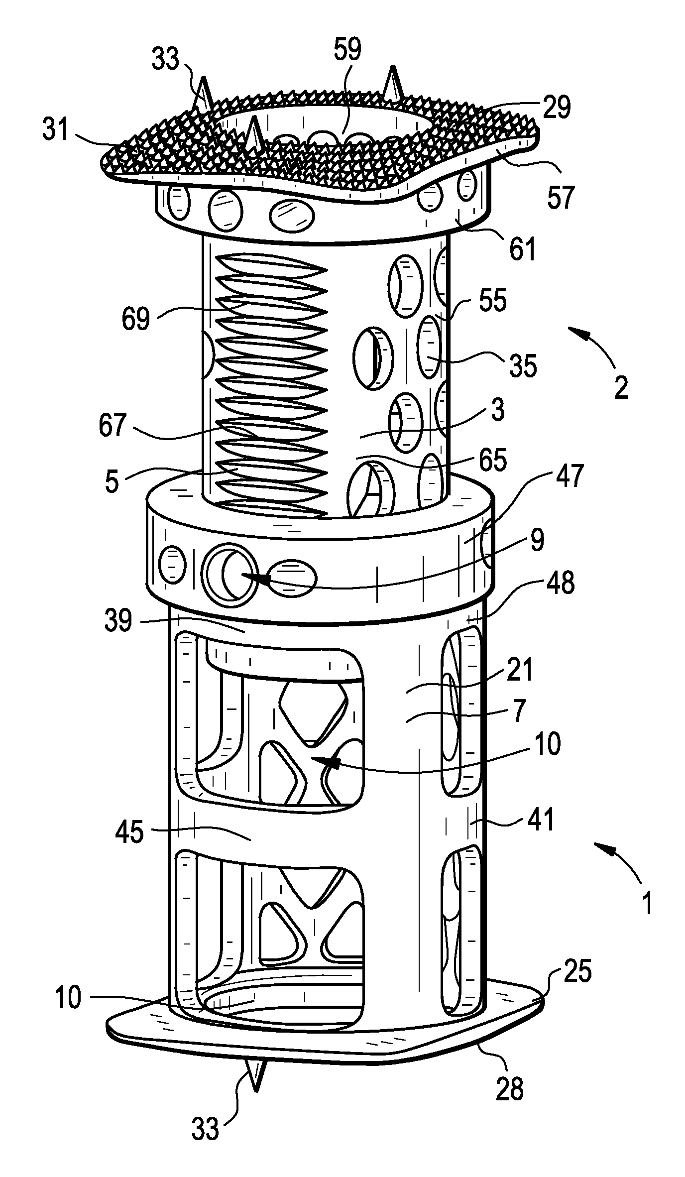
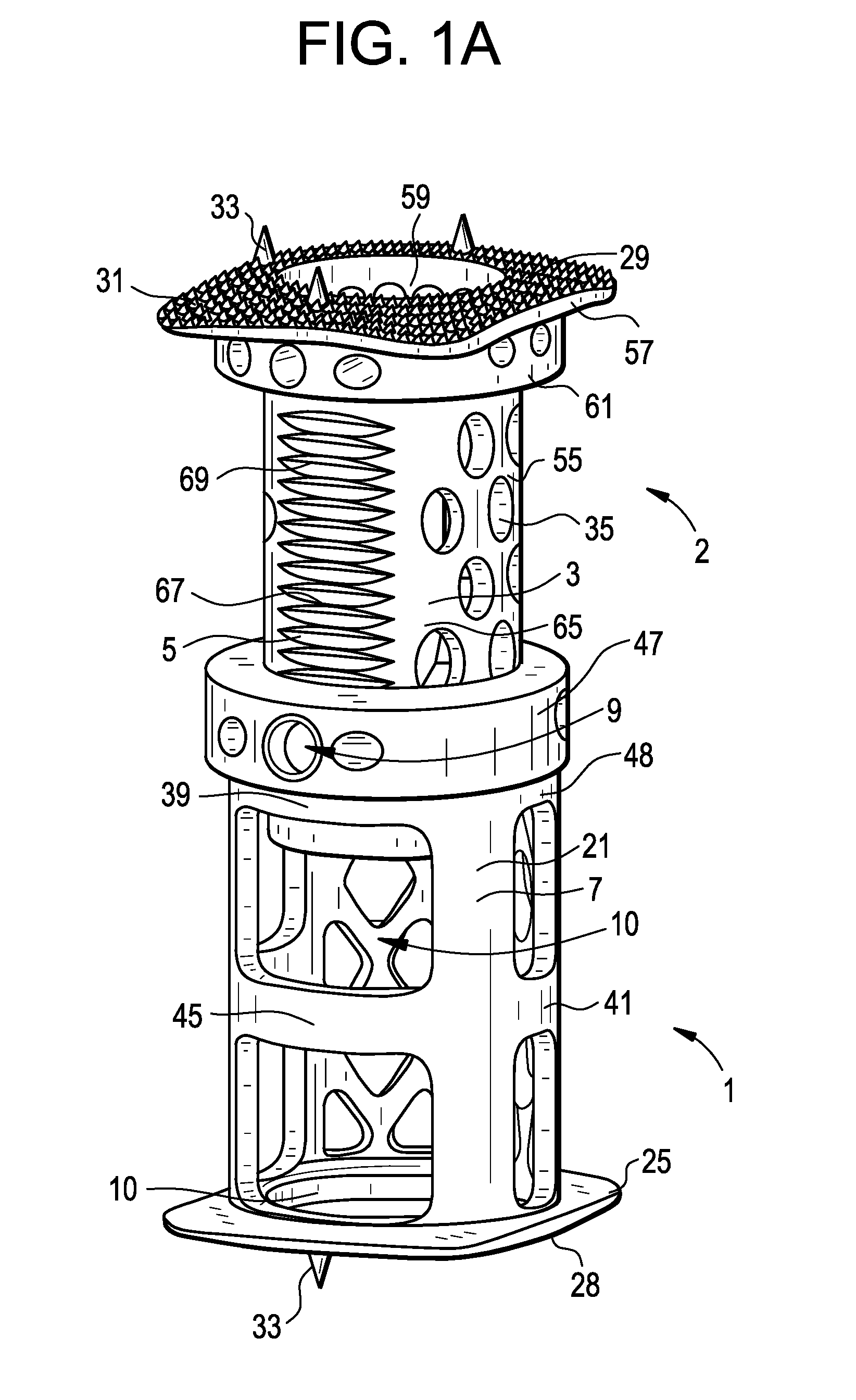
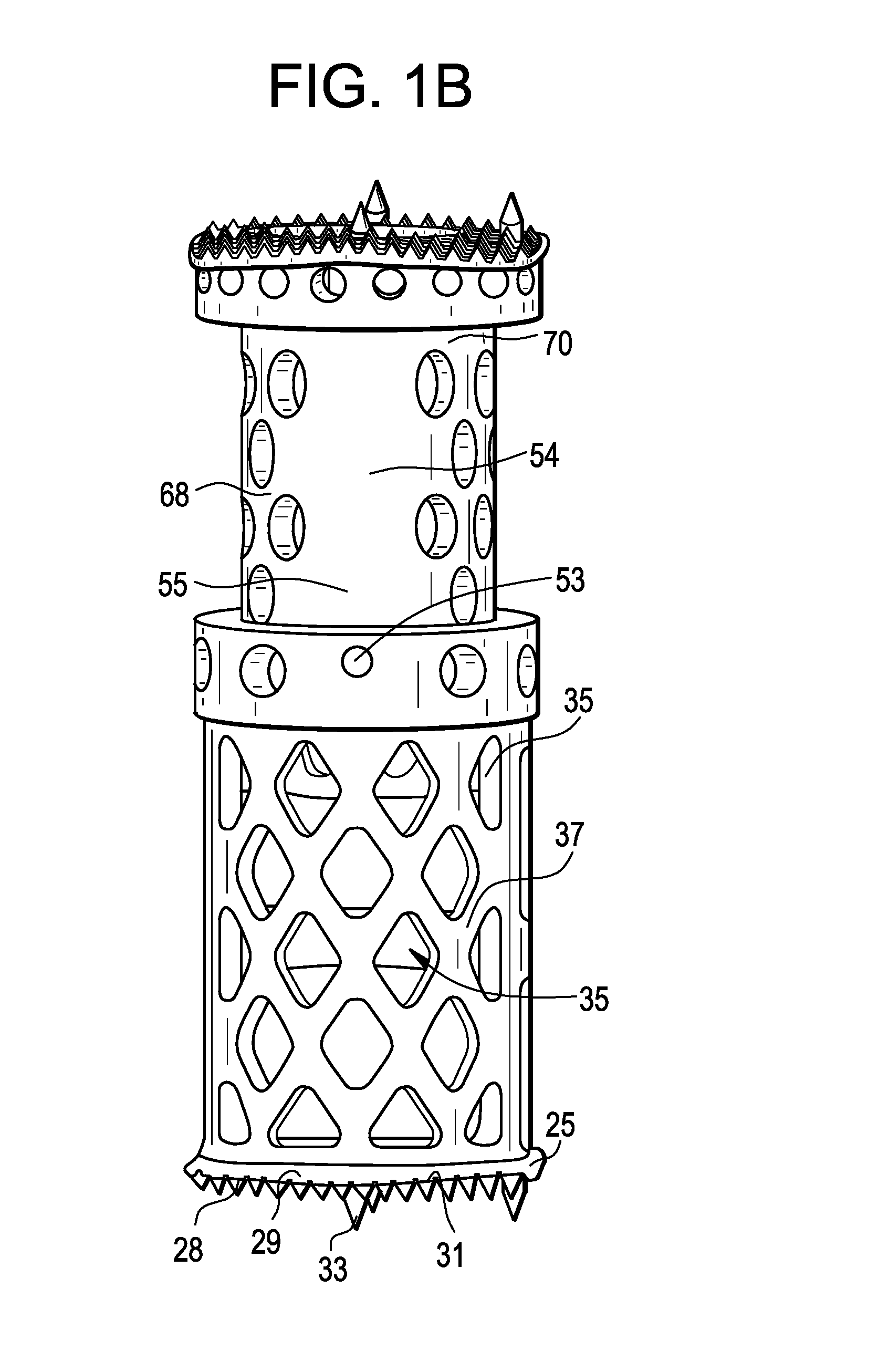
[0033]Now referring to FIG. 1 there is provided a spacer for insertion between two vertebrae, the spacer having a variable axial height and comprising a sleeve-shaped first member 1 and a second member 2 guided within the first member to be slidable relative thereto in an axial direction thereof for adjusting an overall height,

[0034]wherein the second member comprises an outer wall 3 and ratchet notches 5 provided at its outer wall facing the first member and extending in the axial direction, and

[0035]wherein the first member comprises a wall 7 having an engagement member 9, which cooperates with the ratchet notches for adjusting the overall height of the spacer,

[0036]wherein the first member has a window 10 therein for inserting graft material therethrough, and

[0037]wherein the engagement member 9 comprises i) a set screw 11 and ii) a pressure plate 13 having an outer face 15 contacting the...


PUM


Abstract

An intervertebral expandable spacer having a pair of co-axial annuluses locked together by an engagement member having i) a set screw and ii) a pressure plate having an outer face contacting the set screw and an inner face having teeth adapted to mate with the ratchet notches of the second member.

Description

BACKGROUND OF THE INVENTION[0001]One conventional spinal implant used in corpectomy cases is an intervertebral spacer for insertion between two vertebrae, wherein the spacer has an adjustable axial height, an annular first member and a second member which is guided within the first member and displaceable in axial direction relative to the first member for adjustment of the overall height.[0002]Conventional spacers of this type of are often expanded by a threaded connection between the outer surface of the inner member and the inner surface of the outer member. The opposite ends of the spacer are often provided with spikes for secure seating into the adjacent vertebra. However, the requirement of rotating the members around the longitudinal axis also rotates the spikes, thereby risking injury to the adjacent vertebrae.[0003]U.S. Pat. No. 6,200,348 (Biedermann) discloses a spacer that is expandable without the need for rotation. The locking mechanism of the U.S. Pat. No. 6,200,348 in...

Claims


Application Information

Patent Timeline
Patent Type & Authority Applications(United States)
IPC IPC(8): A61F2/44
CPCA61B2017/0256A61F2220/0033A61F2/4611A61F2002/2835A61F2002/30367A61F2002/30507A61F2002/3055A61F2002/30601A61F2002/30784A61F2002/30841A61F2002/4475A61F2002/449A61F2002/4622A61F2002/4628A61F2220/0025A61F2/44A61F2002/30593
Inventor SOMMERICH, ROBERTPRESBREY, GLEN ARTHURMEER, MARTINPOHL, GERHARD FRANZ
Owner DEPUY SYNTHES PROD INC
Learn More