Method of controlling heat in dryer having intake duct with builtin heater

a technology of built-in heaters and intake ducts, which is applied in the direction of drying, lighting and heating equipment, furnaces, etc., can solve the problems of difficult temperature control in the case of controlling on/off of the heater, damage to clothes, etc., and achieve efficient heater control and reduce the difference in temperature

Inactive Publication Date: 2009-07-02
DAEWOO ELECTRONICS CO LTD
View PDF6 Cites 14 Cited by
  • Summary
  • Abstract
  • Description
  • Claims
  • Application Information

AI Technical Summary

Benefits of technology

[0028]According to the present invention, it is possible to operate a plurality of heaters independently of each other depending on a range of drying temperature and also control the heater with temperature control or time control dep

Problems solved by technology

However, as the vertical heater 74 is installed in the inside of the intake duct 70 to shorten the distance between the heater 74 and the drum 60 so as to shorten the flow path of the heated air to reduce the heat loss and prevent the excessive overheat as described above, there is a problem that temperature control is difficult in a case of controlling ON/OFF of the heater by measuring a temperature of discharge air di

Method used


Image

  • Method of controlling heat in dryer having intake duct with builtin heater
  • Method of controlling heat in dryer having intake duct with builtin heater
  • Method of controlling heat in dryer having intake duct with builtin heater

Examples


Embodiment Construction

[0034]Hereinafter, an exemplary embodiment of the present invention will be described with reference to accompanying drawings.

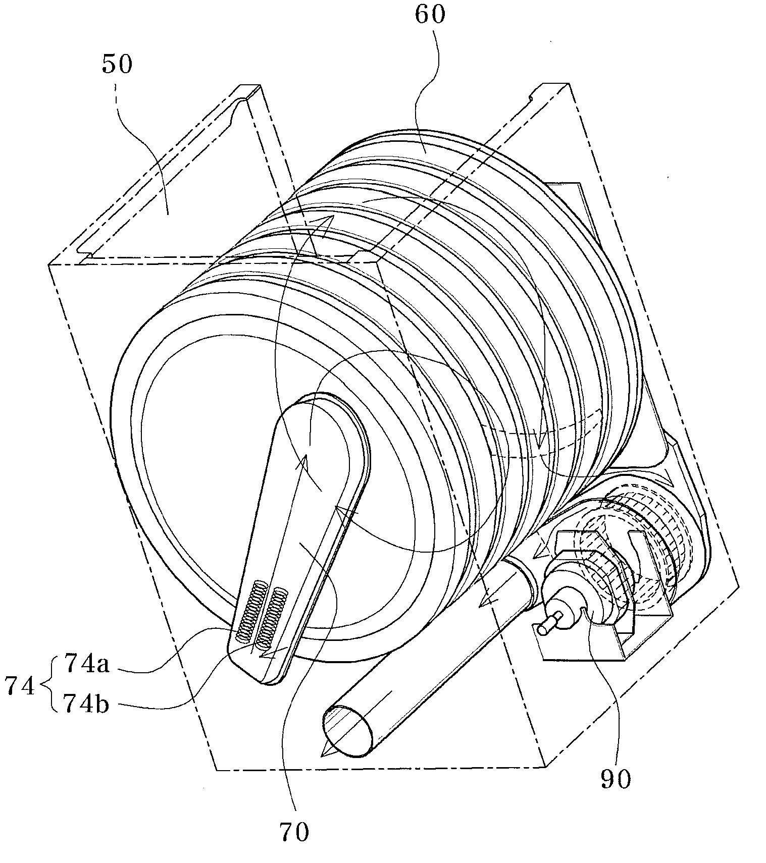
[0035]FIG. 3 is a rear side perspective view illustrating a dryer provided with an intake duct with a builtin heater to which a method of controlling a heater in accordance with an embodiment of the present invention is applied and FIG. 4 and FIG. 5 are a flowchart illustrating a method of controlling a heater of a dryer provided with an intake duct with a builtin heater in accordance with an embodiment of the present invention.

[0036]First, after laundries are putted in a drum 60 of a gas laundry dryer and a door of the dryer is closed, a drying condition is inputted through a key inputting unit. [0037] As the drying condition, one of an ultra low-temperature dry (S20), a low-temperature dry (S30), a middle-temperature dry (S40), a middle high-temperature dry (S50) and a high temperature dry (S60) is selected (S10).

[0037]At this time, when the ultra low-tempe...


PUM


Abstract

A method of controlling a heat in a dryer having an intake duct with a builtin heater operates a plurality of heaters independently of each other depending on a range of drying temperature and also controls the heater with temperature control or time control depending on the range of the drying temperature, thereby reducing difference in a temperature between an intake port of hot wind and a discharge port and allowing efficient heater control by a discharge temperature at the discharge port.

Description

CROSS-REFERENCE TO RELATED APPLICATIONS[0001]The present application claims priority to Korean patent application number 10-2007-0139510, filed on Dec. 27, 2007, which is incorporated by reference in its entirety.BACKGROUND OF THE INVENTION[0002]The present invention relates to a method of controlling a heat in a dryer having an intake duct with a builtin heater, and more particularly, to a method of controlling a heat in a dryer having an intake duct with a builtin heater, which operates a plurality of heaters independently of each other depending on a range of drying temperature and also controls the heater with temperature control or time control depending on the range of the drying temperature, thereby reducing difference in a temperature between an intake port of hot wind and a discharge port and allowing efficient heater control by a discharge temperature at the discharge port.[0003]FIG. 1 is a schematic diagram showing a flow path of a conventional dryer and FIG. 2 is a parti...

Claims


Application Information

Patent Timeline
IPC IPC(8): F26B3/02D06F58/38D06F58/46
CPCD06F58/26D06F58/28D06F2058/2896D06F2058/289D06F2058/2806D06F58/38D06F2103/38D06F2105/28D06F58/46D06F2103/32D06F2103/34D06F58/04
Inventor KIM, CHANG HOO
Owner DAEWOO ELECTRONICS CO LTD
Why Eureka
Try Eureka