Display Means

a technology of display means and means, applied in the field of display means, can solve problems such as graphic damage risk, and achieve the effect of increasing force and decreasing force for

Inactive Publication Date: 2009-07-02
EXPAND INT
View PDF7 Cites 1 Cited by
  • Summary
  • Abstract
  • Description
  • Claims
  • Application Information

AI Technical Summary

Benefits of technology

[0004]The advantage with this solution is that when the pole means is pulled out or pushed in, with a low controlled speed, there is no resistance in the damper means, but when / if the uncontrolled situation described above occurs, the damper means exert a damping force, avoiding the uncontrolled situation.
[0011]According to another embodiment, it is an advantage if said damper means is a liquid damper means, and in that said liquid damper means also comprises a third part arranged at one end of said outer tube, through which third part of said inner tube is running.
[0013]Furthermore, it is an advantage in this context if said first part is arranged in the vicinity of a second end of said inner tube, and is a piston provided with through holes substantially arranged in parallel with said inner tube whereby said liquid is forced to pass said through holes when said tubes are moved in relation to each other.
[0017]Furthermore, it is an advantage in this context if said bobbin is actuated by a spring arrangement adapted to act on said screen with decreasing power of force during a screen wind-up phase and with increasing power of force during a screen unwinding phase.

Problems solved by technology

However, the lock means can be opened by mistake and then the graphics risk to get damaged when the roll up mechanism is pulling the graphics with a high speed in an uncontrollable manner into the cassette.

Method used


Image

  • Display Means
  • Display Means
  • Display Means

Examples


Embodiment Construction

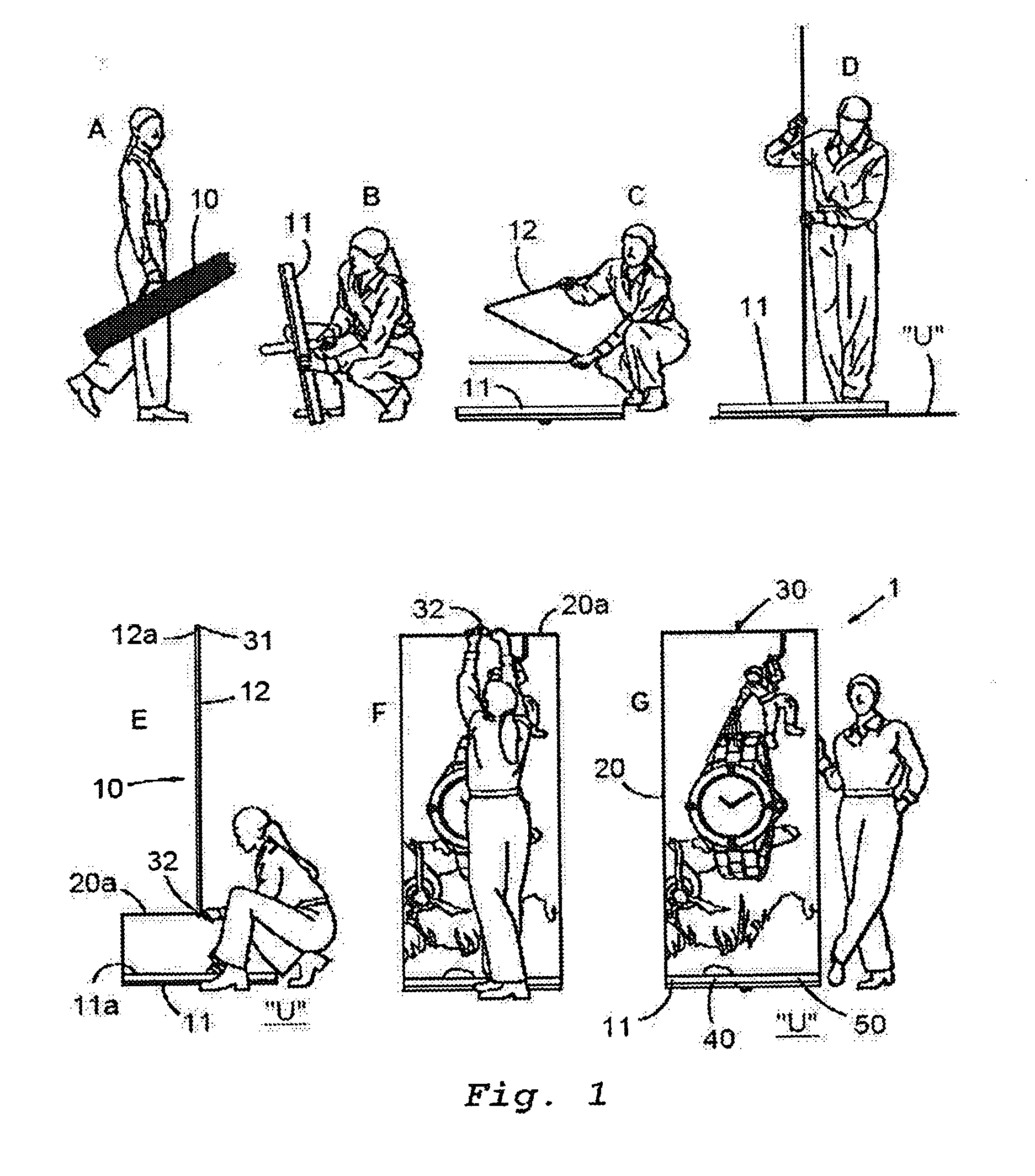
[0024]In FIG. 1 there is disclosed a more or less complete assembly sequence with the aid of individual assembly steps referenced A-G of a display means 1, this assembly sequence or erection sequence also being applicable to the display means 1 according to the present invention.

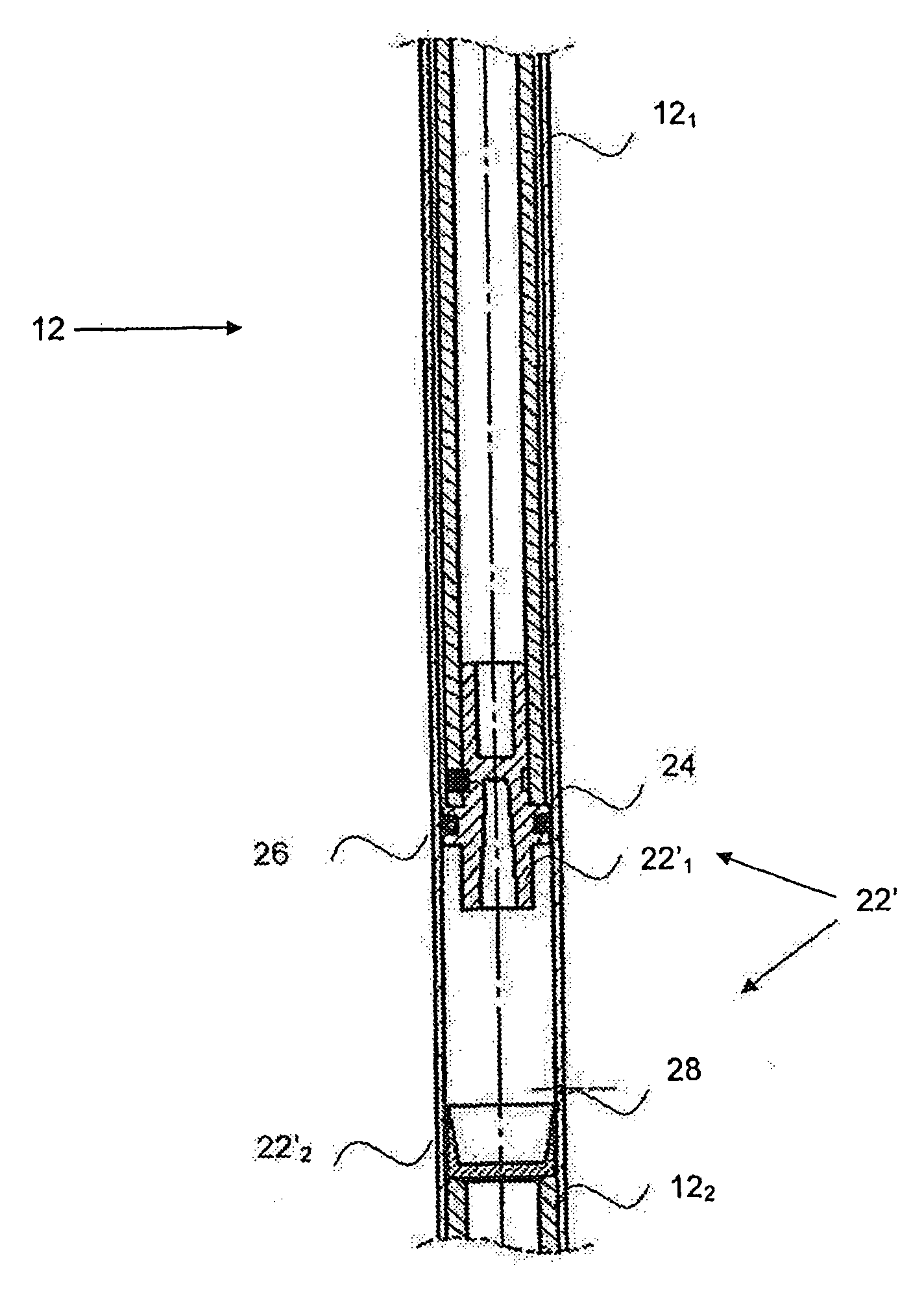
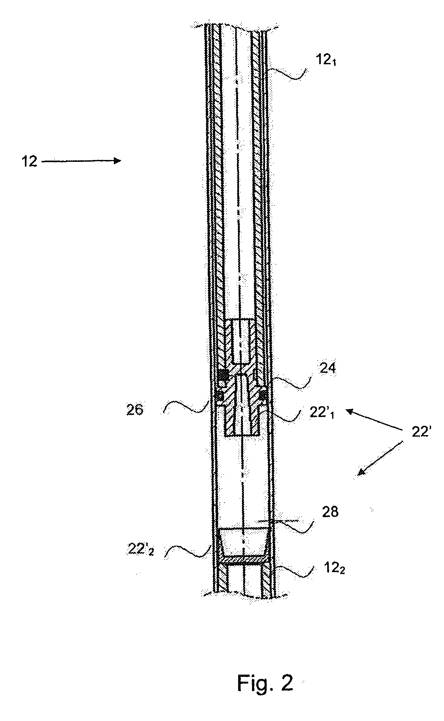
[0025]According to step A, the display means 1 comprises a stand 10, which in a fully erected state (steps F, G) firmly supports a screen 20, wherein the stand 10 comprises a first part 11 which supports against an underlying supportive surface U (step D), and further includes a foldable part 12 which, when the stand 10 is erected, extends upwardly from the first part 11.

[0026]One upwardly extending end part 12a of the second part 12 (step E) has a first coupling element 31 included in a two-part coupling arrangement 30, where—with the other coupling element 32 of the coupling arrangement is joined to the screen 20 either directly or indirectly, and orientated in connection with the upper edge part 20a of th...


PUM


Abstract

The present invention relates to a display means comprising a stand adapted to secure a screen. The stand comprises a first part which supports against an underlying supportive surface and comprises a bobbin enclosed in a cavity in the first part. The screen can be wounded onto and withdrawn from the bobbin. The stand also comprises a telescopic pole means comprising an inner tube and an outer tube, which tubes telescopically can be moved in relation to each other. The stand also comprises a lock means arranged on the inner tube and operable to releasably lock the tubes in relation to each other, a coupling means arranged at a first end of the inner tube and operable to secure the screen when it is at least partly withdrawn from the bobbin, and a damper means comprising a first part arranged on the inner tube, and a second part arranged on the outer tube. The damper means is operable to exert a damping force when the tubes are moved in relation to each other with at least a predetermined threshold velocity value.

Description

TECHNICAL FIELD OF THE INVENTION[0001]The present invention relates generally to a display means and, for instance, more particularly to a display means that includes a readily collapsed and readily erected stand, where the stand used can be adapted to secure a flexible information-presenting screen when in its erected state, and by flexible being meant that the screen can be rolled up onto and unrolled from a bobbin or a rod, normally in the form of a hollow-cylindrical body.BACKGROUND OF THE INVENTION[0002]A telescopic pole with a lock means can be used for holding the printed graphics / screen in a display means (roll up / retractable banner stands) (e.g. Expand QuickScreen). The advantage is that the telescopic pole enables the graphics to be continuously adjusted to a desirable height / size. However, the lock means can be opened by mistake and then the graphics risk to get damaged when the roll up mechanism is pulling the graphics with a high speed in an uncontrollable manner into t...

Claims


Application Information

Patent Timeline
Patent Type & Authority Applications(United States)
IPC IPC(8): G09F15/00
CPCF16F9/0218F16F9/18G09F15/0062G09F7/18G03B21/56G09F15/0037G09F15/0056
Inventor ABERG, ROBERT
Owner EXPAND INT
Why Eureka
Try Eureka