
Fluid flow meter and mixer

a technology which is applied in the direction of measuring devices, volume/mass flow by dynamic fluid flow effect, instruments, etc., can solve the problems of inaccurate downstream measurement of pressure at the downstream side of the displacement member by a tap in the conduit wall, and achieve reliable and repeatable measurement, facilitate the fabrication of flow meter and mixer, and high performance

Inactive Publication Date: 2009-07-02
MCCROMETER
View PDF0 Cites 5 Cited by
  • Summary
  • Abstract
  • Description
  • Claims
  • Application Information

AI Technical Summary

Benefits of technology

[0015]The hollow frustum displacement member of the invention affords the same high performance and flow measurement accuracy as the earlier V-CONE devices, and it provides the advantages of displacement member replaceability and flow measurement at the axis of the downstream face of the displacement member. In addition, and importantly, the hollow frustum displacement member of the invention facilitates fabrication of flow meters and mixers in a more reliable and repeatable fashion to consistently meet preset standards without need for individual testing and calibration.

Problems solved by technology

However, it has since been discovered that for some fluids, especially high velocity gases, measurement of the pressure at the downstream side of the displacement member by a tap in the conduit wall is not as accurate as the downstream measurements obtained with the earlier embodiments of the V-CONE device.

Method used


Image

  • Fluid flow meter and mixer
  • Fluid flow meter and mixer

Examples


Embodiment Construction

[0021]The following is a detailed description of preferred embodiments of the invention presently contemplated by the inventor to be the best mode of carrying out the invention. Modifications and changes will become apparent to persons of reasonable skill in the art as the description proceeds.

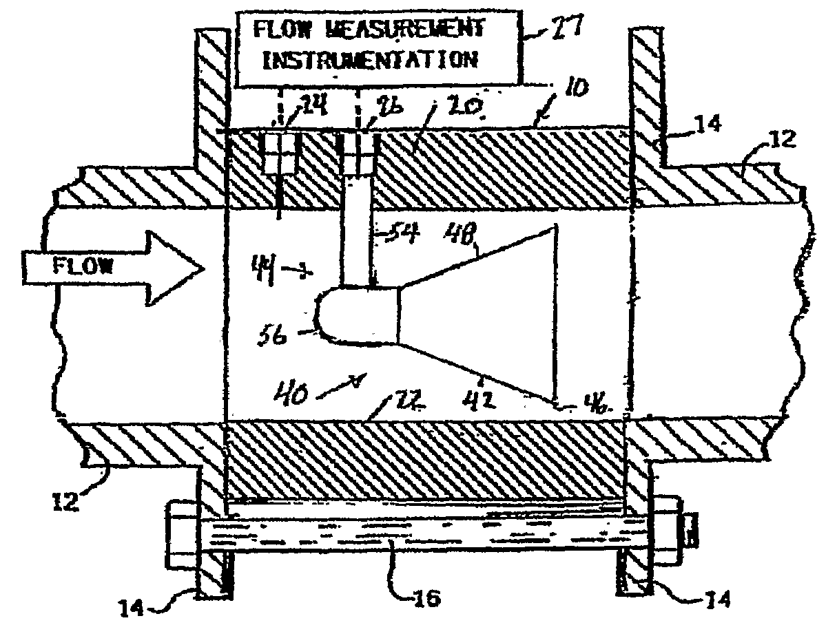
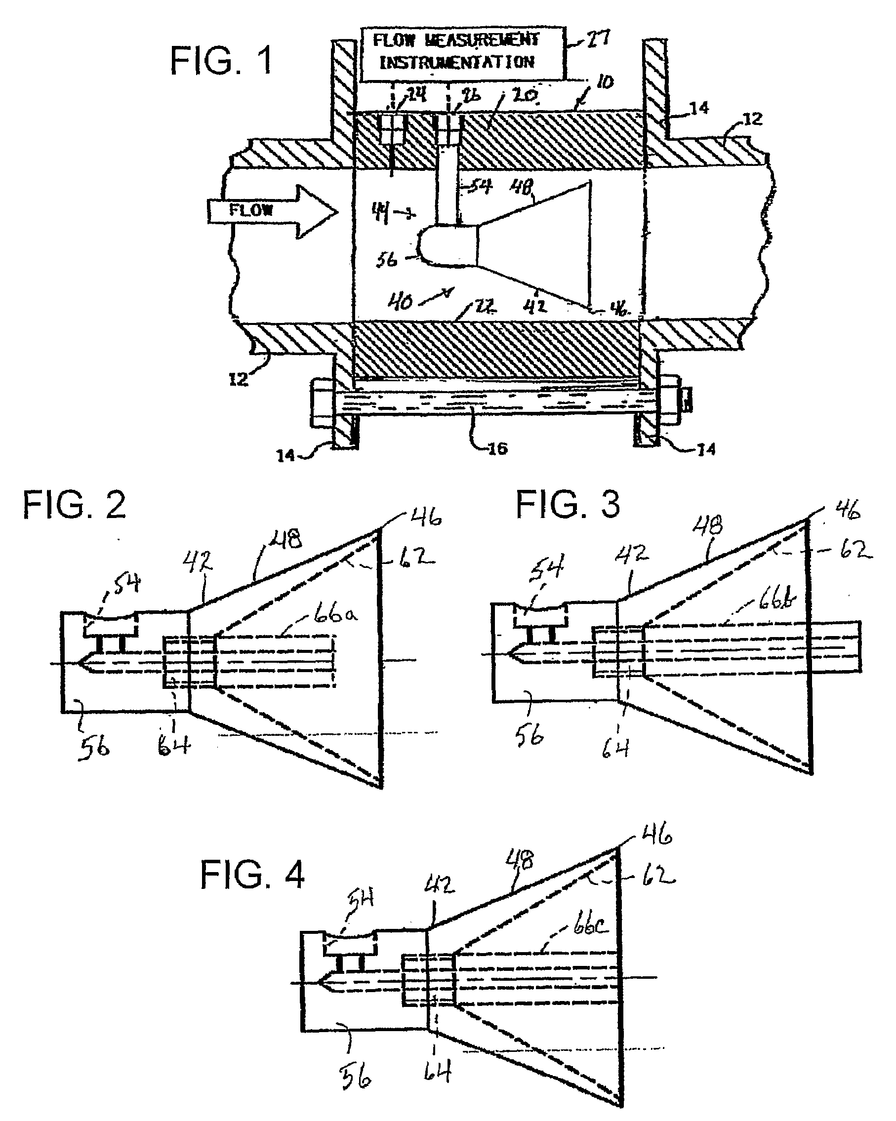
[0022]Referring to FIG. 1, a fluid flow meter made in accordance with the invention, indicated generally at 10, is adapted to be installed in a pipeline or other fluid flow conduit which is depicted as being comprised of pipe sections 12 having bolting flanges 14 at their ends. The flow meter 10 is comprised of a meter body or conduit section 20 and a fluid flow displacement device 40 mounted coaxially within the body. The meter body 20 comprises, in essence, a section of pipe or conduit adapted to be bolted or otherwise secured between two sections of pipe, for example, between the flanges 14 of the illustrated pipe sections 12. The meter body illustrated, by way of example, is of the so call...


PUM


Abstract

Fluid flow apparatus, such as a fluid flow meter, a fluid mixing device or a fluid dispersing device, includes a fluid displacement member (40) mounted in a conduit (20) and having a sloped exterior wall (48) forming a periphery on the member for deflecting the fluid to flow through a region of progressively decreasing area defined between the periphery of the member and the interior surface of the conduit. The displacement member is a hollow frustum (42) terminating at the plane of its outer peripheral edge (46) and accommodating flow measurements at or adjacent the axis of the conduit at or adjacent the plane of the peripheral edge of the displacement member.

Description

TECHNICAL FIELD[0001]The present invention relates to fluid flow apparatus and, in particular, to fluid flow meters, fluid mixers and fluid dispersing devices.BACKGROUND ART[0002]U.S. Pat. Nos. 4,638,672, 4,812,049, 5,363,699 and 5,814,738, and co-pending International Patent Application No. PCT / US2004 / 025900 disclose fluid flow meters and fluid dispersing and mixing devices which are characterized by a unique static fluid flow displacement member which is mounted symmetrically within a conduit and which is effective to linearize fluid flow through the conduit within a region defined between the displacement member and the interior surface of the conduit and to flatten the velocity profile of fluid flow in the conduit both upstream and downstream from the displacement member.[0003]The apparatus ensures reliable measurement of fluid flow conditions within the conduit and also provides for homogeneous blending of diverse fluids and / or fluids containing particulate matter.[0004]The uni...

Claims


Application Information

Patent Timeline
IPC IPC(8): G01F1/42
CPCG01F15/00G01F1/40
Inventor PETERS, ROBERT J.W.MCCALL, FLOYDGONGAWARE, JOYANN
Owner MCCROMETER
Learn More