
Integrated telemetering irrigation region flowmeter

A technology of flow meter and irrigation area, which is applied in the field of hydrological data recording devices, can solve the problems of poor control of the dimensional accuracy of water measuring culverts, low accuracy of actual flow measurement, and large amount of on-site construction, so as to facilitate customer management, save manpower, The effect of saving product cost

Pending Publication Date: 2016-10-26
NANJING AUTOMATION INST OF WATER CONSERVANCY & HYDROLOGY MINIST OF WATER RESOURCES +1
View PDF6 Cites 1 Cited by
  • Summary
  • Abstract
  • Description
  • Claims
  • Application Information

AI Technical Summary

Problems solved by technology

There is a plan on the market to build a hydraulic water measuring building on the channel, install a flow meter in the water measuring culvert, and use the area flow velocity method to calculate the flow rate. The main disadvantage of this plan is that it needs to build a hydraulic water measuring building, Large amount of on-site construction, high cost, poor control of the dimensional accuracy of the water measurement culvert, resulting in low accuracy of actual flow measurement
Moreover, for the natural water in the channel of the irrigation area, not only the sand content may be relatively large, but also the entrainment of floating objects may be more, so it is necessary to develop a special irrigation area flow meter to measure the water flow

Method used

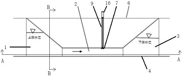
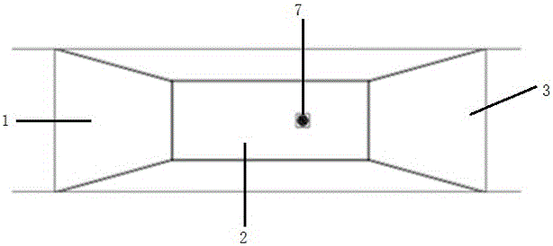
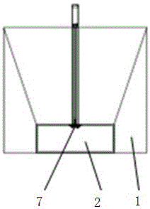

Image

  • Integrated telemetering irrigation region flowmeter
  • Integrated telemetering irrigation region flowmeter
  • Integrated telemetering irrigation region flowmeter

Examples


Embodiment Construction

[0018] The technical solutions provided by the present invention will be described in detail below in conjunction with specific examples. It should be understood that the following specific embodiments are only used to illustrate the present invention and are not intended to limit the scope of the present invention.

[0019] figure 1 , figure 2 , image 3 The cross-sectional schematic diagram of the integrated telemetering irrigation area flowmeter provided by the present invention adopts the plate-like assembled design form, and the whole is in the shape of a cuboid. The upstream guide pipe 1, the water measuring pipe 2 and the downstream guide pipe 3 are formed by splicing the plates. The flow pipe 1 is set in the upstream direction of the water measuring pipe. The material can be fiberglass or stainless steel. It is composed of a bottom plate, a side plate and a top plate. And the function of diversion, the upper edge of the top plate is flush with the top 6 of the chann...


PUM


Abstract

The invention discloses an integrated telemetering irrigation region flowmeter which comprises an upstream honeycomb duct, a water measuring pipe, a downstream honeycomb duct, a flow sensor, an acquisition module, a communication module and a storage battery, wherein the tail end of the upstream honeycomb duct is connected with one end of the water measuring pipe, the head portion of the downstream honeycomb duct is connected with the other end of the water measuring pipe, the flow sensor is connected with the acquisition module, the acquisition module is connected with the communication module, the storage battery supplies power to electrical elements, and the flow sensor comprises a base plate, a rotor, a tongue tube, magnetic steel and a plurality of semiangle rotary cups. The base plate is fixed on the top of the water measuring pipe, and the semiangle rotary cups are arranged under the base plate and fixed on the rotor. A diversion member is arranged under the base plate, and the diversion member and the semiangle rotary cups are placed in the water measuring pipe. The magnetic steel is fixed on the rotor and excites the tongue tube to generate on-off signals, and the tongue tube is connected with the acquisition module. Plate-shaped splicing structures are employed to form gradual changing type honeycomb ducts. A special flow sensor is placed in the water measuring pipe. The measurement is accurate, and on-site installation is simple and fast.

Description

technical field [0001] The invention belongs to the technical field of hydrological data recording devices, and in particular relates to an irrigation area flowmeter with integrated design and remote measurement function. Background technique [0002] Canal irrigation, also known as surface irrigation, is currently the main irrigation method for rice irrigation areas in my country. Rice is the largest water-consuming crop in China and consumes about 50% of the country's total water consumption. Water use efficiency can efficiently save a lot of water resources. In order to improve the water use efficiency of rice, it is necessary to calculate the flow rate during the irrigation of rice channels more accurately. Currently, channel flowmeters sold on the market are mainly aimed at main channel applications. These flowmeters are rarely used in small and medium terminal channels, and the flow (water volume) measurement of small and medium terminal channels is directly related to...

Claims


Application Information

Patent Timeline
Patent Type & Authority Applications(China)
IPC IPC(8): G01F1/05
CPCG01F1/05
Inventor 智永明毛春雷韩继伟刘巽民
Owner NANJING AUTOMATION INST OF WATER CONSERVANCY & HYDROLOGY MINIST OF WATER RESOURCES
Learn More