Radioactive liquid waste treatment device

A radioactive waste and processing device technology, applied in radioactive purification, nuclear engineering, etc., can solve the problems of increasing processing investment and pressure, increasing the difficulty of tail gas processing, and occupying a large storage space, so as to ensure the discharge of the standard and completely remove the remaining radioactive substances , fast response effect

Active Publication Date: 2011-09-28
HUANCHUANG XIAMEN TECH
View PDF5 Cites 20 Cited by
  • Summary
  • Abstract
  • Description
  • Claims
  • Application Information

AI Technical Summary

Problems solved by technology

For the cement solidification method, radioactive waste is directly compressed and sealed with cement, which faces various challenges due to its large capacity expansion ratio, high storage cost, and large storage space.
For the incineration and filtration method, after incineration and filtration of radioactive waste, although the storage space can be alleviated to a large extent, and the storage cost will be reduced accordingly, but the pollution of the environment due to the dioxin produced by the incineration cannot be underestimated. At the same time, the current incineration method has a very large structure. In addition to the high investment intensity, its fixed structure has brought the disadvantages that the radioactive waste contained in each power station must be transferred to the volume reduction treatment center for treatment, which virtually increases the number of radioactive wastes. Due to the limitation of the heating method, the nuclides in the radioactive waste form aerosols and drift with the hot air flow during incineration, which not only increases the difficulty of tail gas treatment, but also increases the investment and pressure of treatment, which may further lead to secondary pollution. one or more pollution

Method used


Image

  • Radioactive liquid waste treatment device
  • Radioactive liquid waste treatment device
  • Radioactive liquid waste treatment device

Examples


Embodiment Construction

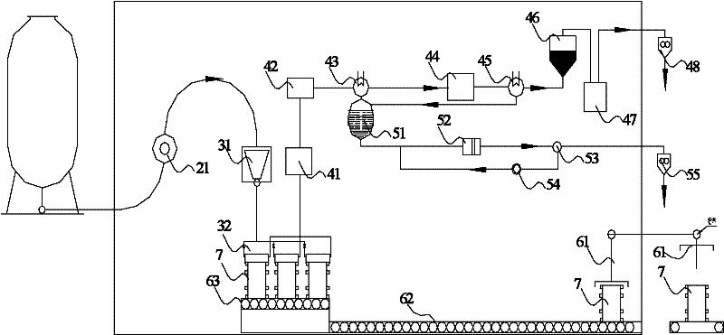
[0015] see figure 1 , the present invention provides a radioactive waste treatment device, including a feeding device for supplying liquid radioactive waste, a volume reduction device for radioactive waste, tail gas and residual liquid formed after the radioactive waste is processed by the volume reduction device, and The raffinate treatment device, the transportation device for the treated radioactive waste after being treated by the volume reduction device; the feeding device, the tail gas and raffinate processing device and the transportation device are respectively connected to the volume reduction device through pipelines; the feeding device , tail gas and residual liquid treatment device, transportation device and volume reduction device are in a vacuum environment as a whole.

[0016] The radioactive waste volume reduction device includes a drying volume reduction device for efficiently removing moisture in radioactive waste. The volume reduction unit is mainly composed...


PUM


Abstract

The invention relates to a radioactive liquid waste treatment device comprising a feeding device, a volume reducer of radioactive wastes, a tail gas and residual liquid treatment device and a conveyer. The feeding device, the tail gas and residual liquid treatment device and the conveyer are respectively connected with the volume reducer; the feeding device, the tail gas and residual liquid treatment device, the conveyer and the volume reducer are integrally arranged under a vacuum environment; the volume reducer comprises a macroscopic dehydration volume-reduction unit for macroscopically dehydrating and reducing volume of the radioactive liquid wastes and a heating-drying volume-reduction unit, and the heating-drying volume-reduction unit and the macroscopic dehydration volume-reductionunit for breaking the organization structure of the radioactive wastes are connected by a pipeline to form a seal system. A movable radioactive liquid waste treatment device disclosed by the invention has the advantages of little environment pollution, safe and reliable treatment process and reduced storage space, and reaches the state standard of effluent discharge.

Description

technical field [0001] The invention belongs to the field of radioactive waste treatment, and relates to a treatment device for various radioactive liquid wastes, in particular to a variety of liquid radioactive concentrates, radioactive silt, radioactive water-saturated resin and other liquid radioactive materials produced in the process of nuclear industry and nuclear power plant nuclear reactors Waste disposal unit. Background technique [0002] As an efficient and clean energy, nuclear power has been increasingly valued and utilized by people. As of 2010, there were 13 nuclear power units in operation in mainland my country, and 24 units under construction will also be put into commercial operation successively. While nuclear power brings huge economic benefits to people, the technological waste and technical waste produced in the working process have certain radioactivity. For example, in addition to producing technological waste concentrate, sludge and waste water-satu...

Claims


Application Information

Patent Timeline
Patent Type & Authority Applications(China)
IPC IPC(8): G21F9/04G21F9/20G21F9/06G21F9/08G21F9/12G21F9/22
Inventor 张喜华王武尚李进黄来喜何文新浣石
Owner HUANCHUANG XIAMEN TECH
Why Eureka
Try Eureka