Acoustic load mitigator

Inactive Publication Date: 2009-07-02
GE HITACHI NUCLEAR ENERGY AMERICAS
View PDF24 Cites 2 Cited by
  • Summary
  • Abstract
  • Description
  • Claims
  • Application Information

AI Technical Summary

Benefits of technology

[0007]In one embodiment of the invention, a system for reducing an acoustic load of a fluid flow comprises a first pipe to carry the fluid flow; a standpipe connected to the first pipe at an ope

Problems solved by technology

One of the sources of loading that has destroyed or damaged equipment is acoustic resonance of the fluid inside a standoff pipe, such as a safety relief valve.
The safety relieve valve, or valves, with steam flow past their entrances, and the acoustic resonance which naturally

Method used


Image

  • Acoustic load mitigator
  • Acoustic load mitigator
  • Acoustic load mitigator

Examples


Example

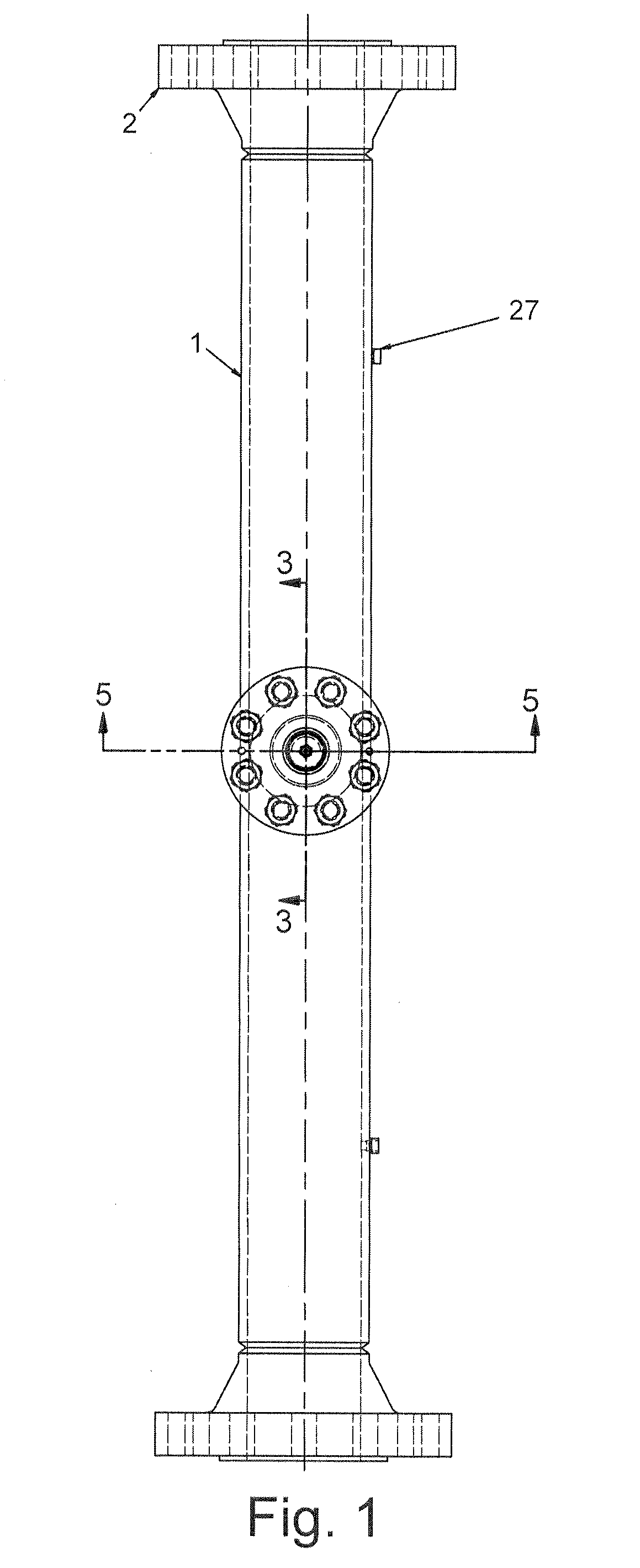
[0019]Referring to FIGS. 1-5, a steam line pipe 1, for example, in a nuclear power generating station such as a boiling water reactor (BWR) comprises pipe flanges 2 at opposite ends for connection of the steam line pipe 1 to a steam delivery line. A pressure sensor 27 may be provided in the steam line pipe 1 to measure a pressure of steam carried by the steam line pipe 1.

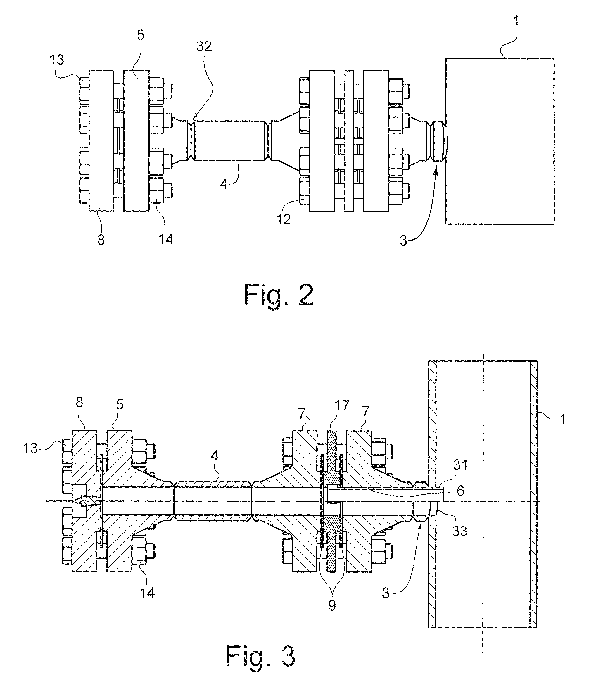
[0020]A standpipe 32 is connected to the steam line pipe 1 for mounting of a safety relief valve (not shown) to a pipe flange 8 of the standpipe 32. A pressure sensor 28 is provided on the pipe flange 8 to measure pressure of the steam in the standpipe 32.

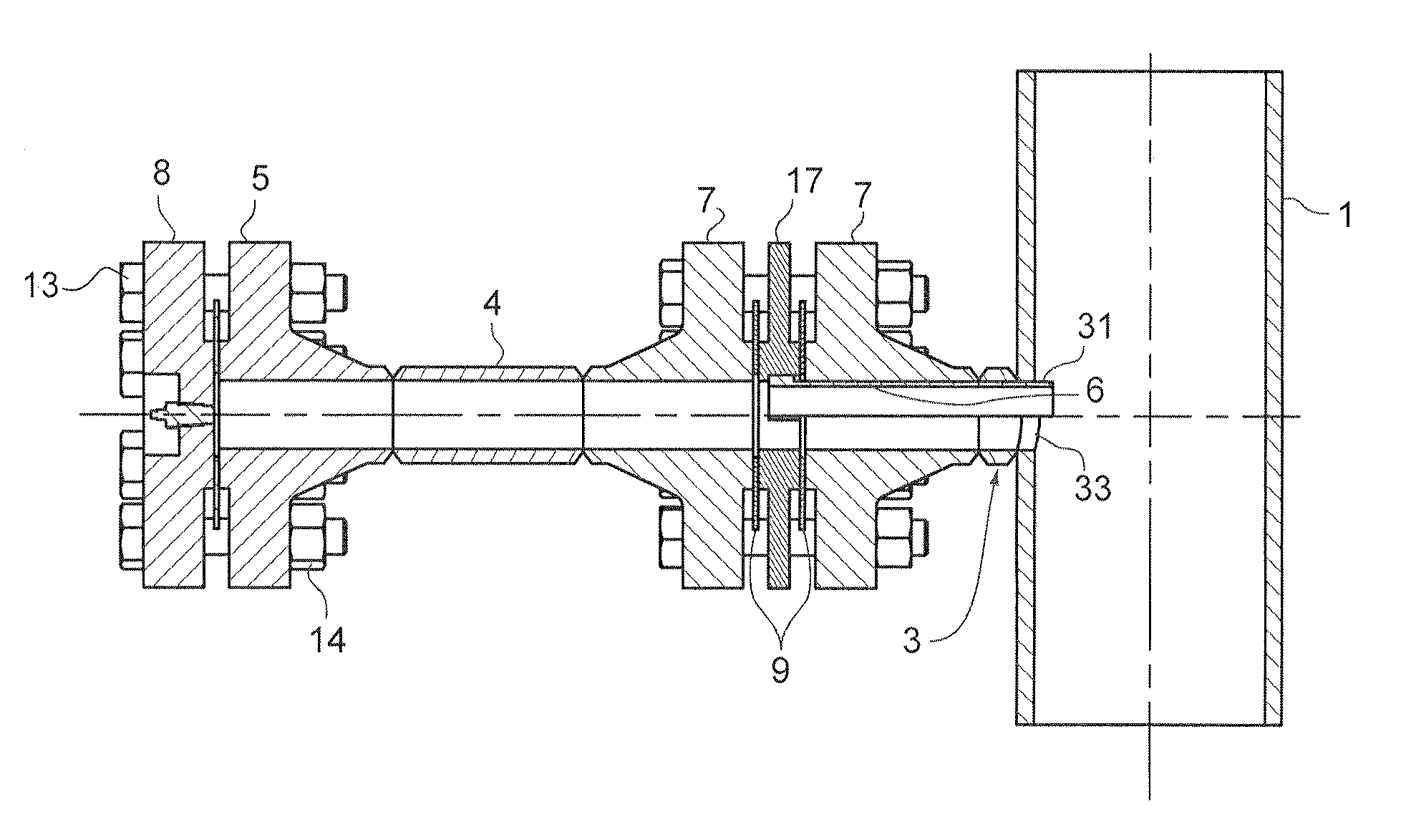
[0021]Referring to FIGS. 3-5, the standpipe 32 may be connected to the steam line pipe 1 by a pipe base 3. A first pipe flange 7 is connected to the pipe base 3. A second pipe base 7 is connected to the first pipe flange 7 by fasteners, for example bolts 12 and nuts 14. A spacer 17 is provided between the first and second pipe flanges 7. Each side of the spacer 17 ...


PUM


Abstract

A system for reducing an acoustic load of a fluid flow includes a first pipe to carry the fluid flow; a standpipe connected to the first pipe at an opening in the first pipe; and a standpipe flow tripper provided in the standpipe. The flow tripper includes an edge extending through the opening into the flow on a downstream side of the opening. A method of reducing an acoustic load of a standing wave in a standpipe connected to a first pipe configured to carry a flow includes disrupting the flow in the first pipe at a downstream side of an opening in the first pipe to which the standpipe is connected.

Description

BACKGROUND OF THE INVENTION[0001]The present invention relates generally to nuclear reactors, and more particularly to mitigating acoustic loads in a nuclear reactor.[0002]In boiling water nuclear reactor (BWR), reactor coolant flows through a series of plenums starting with a lower core plenum, the nuclear core itself and an upper core plenum, each lying in communication with one another. The upper core plenum lies below a shroud head which has a series of standpipes that lead steam / water to a series of separators where the two-phase mixture of steam and water is separated. The separated water flows downwardly in an annulus about the core shroud for recirculation. The separated steam flows upwardly of the reactor through a steam dryer for flow outside of the reactor vessel to drive a turbine for generating power.[0003]In BWR's, this flowing mixture of vapor and liquid must be separated efficiently to provide the dry steam required for steam turbine generators. Typical reactor desig...

Claims


Application Information

Patent Timeline
IPC IPC(8): F01N1/00
CPCF16L55/04
Inventor LYNCH, JOHN J.
Owner GE HITACHI NUCLEAR ENERGY AMERICAS
Why Eureka
Try Eureka