Acoustic load mitigator

Active Publication Date: 2009-05-21
GE HITACHI NUCLEAR ENERGY AMERICAS
View PDF13 Cites 8 Cited by
  • Summary
  • Abstract
  • Description
  • Claims
  • Application Information

AI Technical Summary

Benefits of technology

[0009]In one embodiment of the invention, a system for reducing an acoustic load of a fluid flow comprises a first pipe. The first pipe comprises a first end and a second end and a first aperture and a second aperture. The first and second apertures are intermediate the first and second ends. A second pipe comprises a first

Problems solved by technology

The flow of steam through the dryers can be unbalanced or mismatched, with much of the steam flow preferentially passing through the top of the dryer vanes.
At increased power levels of the reactor, increased steam flow may cause the steam velocity to exceed the breakthrough velocity in local regions of the dryer vanes.
Wet steam that breaks through, or exits the dryer, then can cause undesirable effects in the rest of the power plant.
In addition to the potential for erosion of the metal components, the excess moisture can transport activated particulates from the reactor to the pipes, turbines and heat exchangers which are downstream of the separat

Method used


Image

  • Acoustic load mitigator
  • Acoustic load mitigator
  • Acoustic load mitigator

Examples


Example

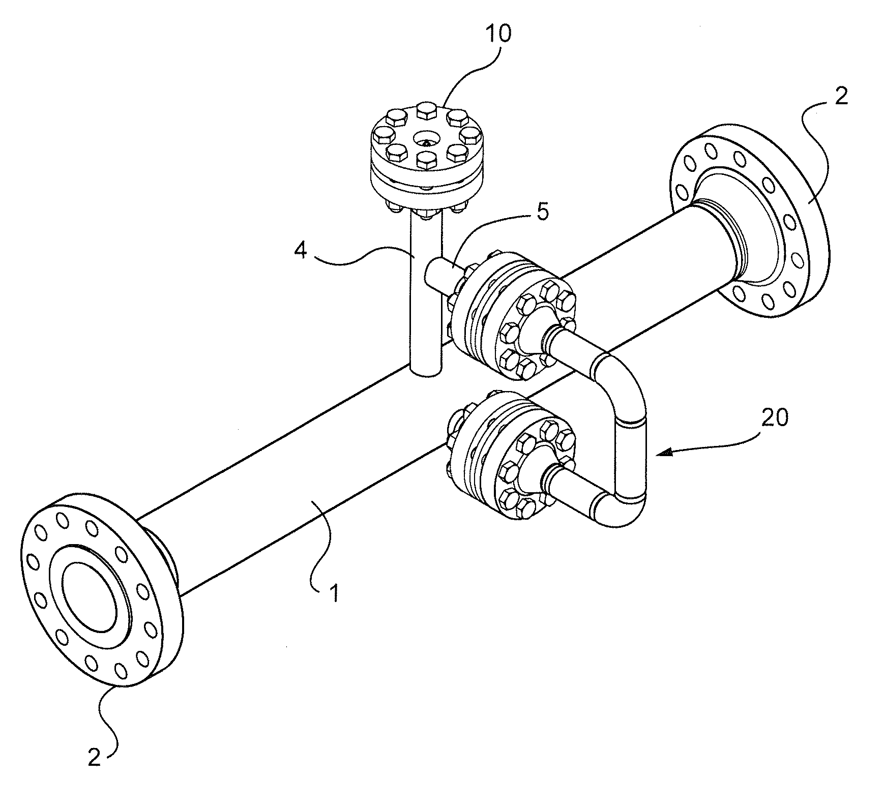
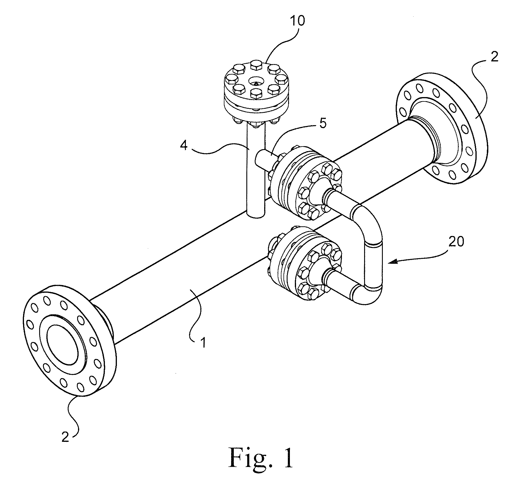
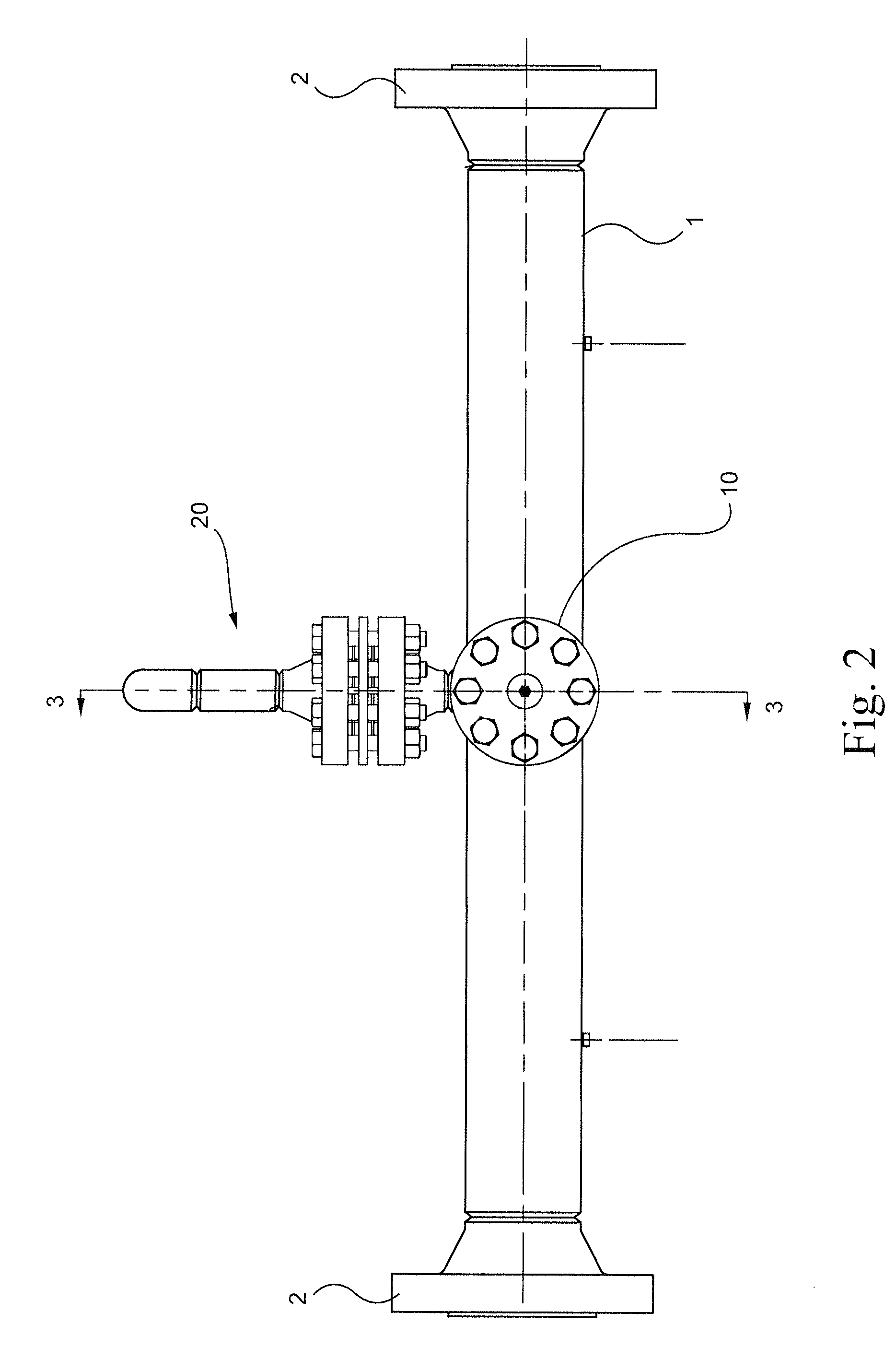
[0016]Referring to FIGS. 1-3, a steam line pipe 1, for example, in a nuclear power generating station such as a boiling water reactor (BWR) comprises pipe flanges 2 at opposite ends for connection of the steam line pipe 1 to a steam delivery line. A pressure sensor 18 may be provided in the steam line pipe 1 to measure a pressure of steam carried by the steam line.

[0017]A standoff pipe 4 is connected to a first outlet 21 of the steam line pipe 1 for mounting of a safety relief valve (not shown) to a pipe flange 10 provided on the standoff pipe 4. A pressure sensor 23 is provided on the pipe flange 10 to measure pressure of the steam in the standoff pipe 4. A bypass pipe 20 is connected to the steam line pipe 1 and the standoff pipe 4.

[0018]Referring to FIG. 3, the bypass pipe 20 is connected at one end to the steam line pipe 1 at a second outlet 24 of the steam line pipe 1 by a pipe base 3. The bypass pipe 20 is connected at the other end to the inlet 22 of the standoff pipe 4 by a ...


PUM


Abstract

A system for reducing an acoustic load of a fluid flow includes a first pipe. The first pipe includes a first end and a second end and a first aperture and a second aperture, the first and second apertures being intermediate the first and second ends. A second pipe includes a first end and a second end and a third aperture intermediate the first and second ends. The second pipe is connected at its first end to the first pipe at the first aperture. A bypass pipe includes a first end connected to the second aperture of the first pipe and a second end connected to the third aperture of the second pipe. A method of reducing an acoustic load of a flow in a standpipe connected to a first pipe configured to carry a main flow includes providing a bypass flow from the first pipe to the standpipe.

Description

BACKGROUND OF THE INVENTION[0001]The present invention relates generally to nuclear reactors, and more particularly to mitigating acoustic loads in a nuclear reactor.[0002]A reactor pressure vessel (RPV) of a boiling water reactor (BWR) typically has a generally cylindrical shape and is closed at both ends, e.g., by a bottom head and a removable top head. A top guide typically is spaced above a core plate within the RPV. A core shroud, or shroud, typically surrounds the core and is supported by a shroud support structure. Particularly, the shroud has a generally cylindrical shape and surrounds both the core plate and the top guide. There is a space or annulus located between the cylindrical reactor pressure vessel and the cylindrically shaped shroud.[0003]Heat is generated within the core and water circulated up through the core is at least partially converted to steam. Steam separators separate the steam and the water. Residual water is removed from the steam by steam dryers locate...

Claims


Application Information

Patent Timeline
IPC IPC(8): F15D1/02F01N1/02
CPCF16L55/033G21C19/00G21C1/084F16L55/041
Inventor LYNCH, JOHN J.
Owner GE HITACHI NUCLEAR ENERGY AMERICAS
Why Eureka
Try Eureka