Self-position identifying method and device, and three-dimensional shape measuring method and device

a self-positioning and measurement method technology, applied in the field of self-position identification methods and devices, and three-dimensional shape measurement methods and devices, can solve the problems of limited range, inconvenient measurement, and inability to accurately measure, and achieve the effects of accurate matching, excellent memory efficiency, and stable in regards to inadequate point quantities and errors in measured data

Inactive Publication Date: 2009-07-02
IHI CORP
View PDF3 Cites 35 Cited by
  • Summary
  • Abstract
  • Description
  • Claims
  • Application Information

AI Technical Summary

Benefits of technology

[0041]The present invention was invented to resolve the problems described above. That is, the object of the present invention is to provide a self-position identifying method and device, and to a three-dimensional shape measuring method and device capable of performing the calculations for position identification efficiently, having a data structure for the surrounding environment with excellent memory efficiency, and being stable in regards to inadequate point quantities and error in the measured data. The self-position identifying method and device, and the three-dimensional shape measuring method and device are able to perform accurate matching, with a little calculation amount, without cumulative error, even when there is a discrepancy in the positions in each measurement, with no corresponding points and a relatively large degree of included error, where the external three-dimensional data is a spatially dispersed point set.

Problems solved by technology

However, while these means have the benefit of being able to identify stable positions, they have the problems of requiring infra structure, having a limited range over which positions can be identified, requiring work in installation, and so forth.
However, ultrasonic sensors have the problems of having a narrow measurement scope and poor accuracy, while image sensors have the problem of being susceptible to the impact of lighting conditions.
Moreover, with this type of range sensor, typically there is error of about ±20 cm in the measured distances.
That is, the range data that is obtained is a set of points that is dispersed in the horizontal direction and the vertical direction, and position is different for each measuring, so that there are not corresponding positions, and measured distance includes a relatively large error.
(1) Cumulative Error
The ICP algorithm is the means for superimposing two range data, and even though the earlier data and the later data are compared repetitively and the differences are integrated, there are essentially no corresponding points, so the error is cumulative.
(3) Lack of Suitability If There Are Few Measured Points
The ICP algorithm is used for dense range data, so when the point set is dispersed and spatially sparse, the algorithm will converge to incorrect results.

Method used


Image

  • Self-position identifying method and device, and three-dimensional shape measuring method and device
  • Self-position identifying method and device, and three-dimensional shape measuring method and device
  • Self-position identifying method and device, and three-dimensional shape measuring method and device

Examples


Embodiment Construction

[0137]A preferred embodiment of the present invention will be explained below in reference with the drawings. Note that in each drawing, identical portions are assigned identical codes, and redundant explanations are omitted.

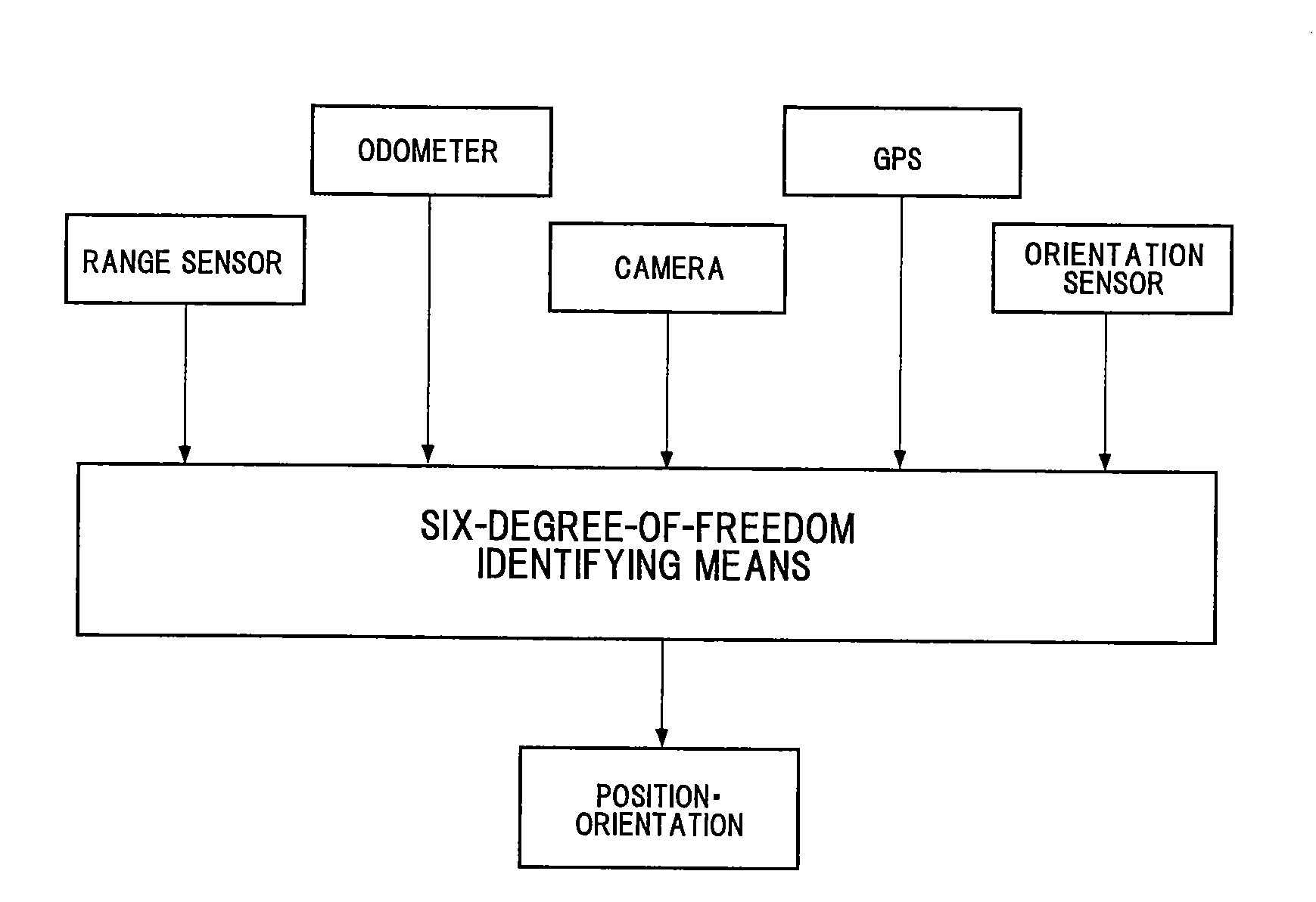
[0138]FIG. 2 is an overall structural diagram of the self-position identifying device as set forth in the present invention. In this figure, the self-position identifying device as set forth in the present invention is six-degree-of-freedom identifying means, a device that identifies the self-position through incorporating three-dimensional information from the outside from a range sensor, an odometer, a camera, a GPS, and an orientation sensor. Note that in the present invention, “self-position” means a position and orientation in six degrees of freedom in the external environment of the self-position determining device.

[0139]Note that in the present invention, the odometer, camera, GPS, and orientation sensor are not indispensable in addition to the range sens...


PUM


Abstract

The invention includes a step S1 for inputting into a computer coordinate values on a three-dimensional shape; a step S4 for structuring an environment model that partitions a spatial region, in which a three-dimensional shape exists, into a plurality of voxels of rectangular solids, and stores each position; and a step S5 for setting and recording a representative point and an error distribution thereof, within the voxel corresponding to the coordinate value. If there is no data in a previous measurement position, position matching is performed in a fine position matching step S7 so as to minimize an evaluation value regarding the distances between adjacent error distributions by rotating and translating a new measurement data and error distribution for the environment model for a previous measuring position, or rotating and translating an environment model for a new measuring position, relative to an environment model for a previous measuring position.

Description

BACKGROUND OF THE INVENTION[0001]1. Technical Field of the Invention[0002]The present invention relates to a self-position identifying method and device, and a three-dimensional shape measuring method and device, by receiving external three-dimensional information.[0003]2. Description of the Related Art[0004]GPS, DGPS, magnetic markers, magnetic methods, radio methods, image marker methods, optical / electromagnetic marker methods, and the like, are known as means or methods for direct identification of self-position. However, while these means have the benefit of being able to identify stable positions, they have the problems of requiring infra structure, having a limited range over which positions can be identified, requiring work in installation, and so forth.[0005]In contrast, there have been a variety of proposals for self-position identifying means that calculate the self-position through comparing newly acquired measured data to environment information that has been acquired th...

Claims


Application Information

Patent Timeline
Patent Type & Authority Applications(United States)
IPC IPC(8): G06T17/00G01S17/89
CPCG01B11/24G01S17/89G06T2207/10016G06T7/0048G06T7/0065G06T7/0046G06T7/75G06T7/77G06T7/55
Inventor HAYASHI, TOSHIHIROKAWANO, YUKIHIROTERADA, HIDEO
Owner IHI CORP
Why Eureka
Try Eureka