Wide-Band Ultrashort-Pulse Optical Oscillator Utilizing Chirped Pulse Amplification
an optical oscillator and ultrashort pulse technology, applied in the field of oscillators, can solve the problems of laser light having an ultrahigh output power and an increase in the output power of the pulse, and achieve the effects of high gain, high degree of efficiency, and mode locking
- Summary
- Abstract
- Description
- Claims
- Application Information
AI Technical Summary
Benefits of technology
Problems solved by technology
Method used
Image

Examples
embodiment 1
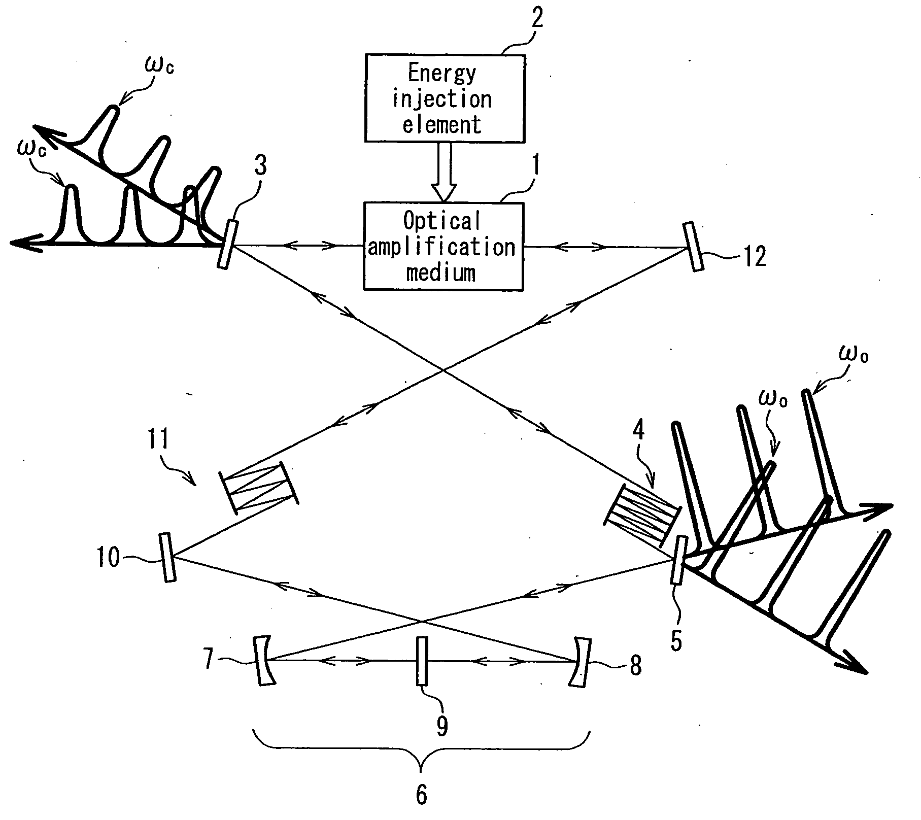
[0058]FIG. 1 is a conceptual diagram illustrating a configuration of a wide-band ultrashort-pulse optical oscillator according to Embodiment 1 of the present invention.
[0059]This optical oscillator includes an optical amplification medium 1, an energy injection element 2, a negative dispersion element 4, a mode-locking part 6, and a positive dispersion element 11. The mode-locking part 6 is composed of a pair of concave mirrors 7 and 8, and a mode locker 9. A pulse light exiting from the optical amplification medium 1 is guided to the negative chirping mirror 4 via a mirror 3, and is incident in the mode-locking part 6 via a mirror 5. The pulse light passes through the concave mirror 7, the mode locker 9, and the concave mirror 8 so as to exit from the mode-locking part 6. Then, after passing through a mirror 10, the positive dispersion element 11, and a mirror 12, the pulse light is incident in the optical amplification medium 1.
[0060]The optical amplification medium 1 has a functi...
embodiment 2
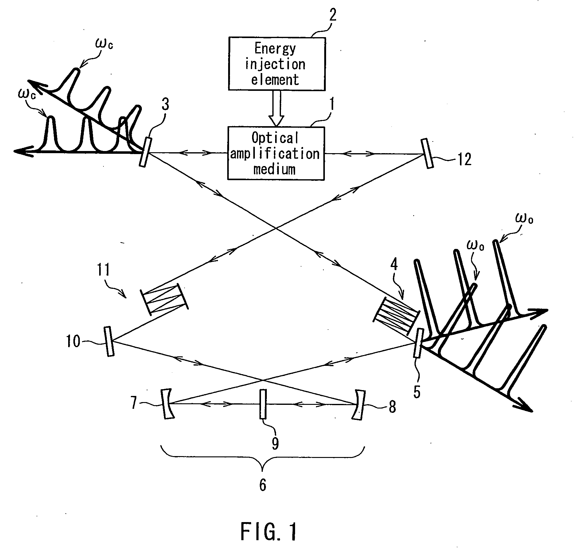
[0069]FIG. 2 is a conceptual diagram illustrating a configuration of a wide-band ultrashort-pulse optical oscillator according to Embodiment 2 of the present invention. In the present embodiment, the optical parametric amplification process is used. It should be noted that the optical oscillator of the present embodiment has a configuration such that the optical amplification medium 1 and the energy injection element 2 in the optical oscillator shown in FIG. 1 are specified to be a nonlinear optical crystal 13 and an excitation light source 14, respectively. Therefore, other elements are similar to those in the case of the optical oscillator shown in FIG. 1; the same elements as those in FIG. 1 are designated by the same reference numerals, and descriptions thereof are not repeated herein.
[0070]In the optical oscillator shown in FIG. 2, a photon energy of an excitation light (ωp) incident in the nonlinear optical crystal 13 from the excitation light source 14 is converted to photon ...
embodiment 3
[0080]FIG. 3A is a conceptual diagram illustrating a configuration of a wide-band ultrashort-pulse optical oscillator according to Embodiment 3 of the present invention. The basic configuration of this oscillator is similar to that shown in FIG. 2; the same elements as those in FIG. 2 are designated by the same reference numerals, and descriptions thereof are not repeated herein.
[0081]In the present embodiment, a frequency modulation part 20 is disposed between a negative chirping mirror 4 and a mode locker 9. As shown in FIG. 3B, the frequency modulation part 20 is composed of a pair of frequency modulators 21 and 22 in the complementary relationship to each other. Further, exiting mirrors 23 and 24 are disposed, which are for taking a modulated light pulse (ωm) out between the pair of frequency modulators 21 and 22. As the frequency modulators 21 and 22, for example, frequency modulators utilizing acousto-optic elements may be used.
[0082]Thus, by interposing the frequency modulato...
PUM
 Abstract
Description
Claims
Application Information
 - R&D Engineer
- R&D Manager
- IP Professional
- Industry Leading Data Capabilities
- Powerful AI technology
- Patent DNA Extraction
Browse by: Latest US Patents, China's latest patents, Technical Efficacy Thesaurus, Application Domain, Technology Topic.
© 2024 PatSnap. All rights reserved.Legal|Privacy policy|Modern Slavery Act Transparency Statement|Sitemap