Fixing Device

a fixing device and fixed belt technology, applied in the direction of instruments, electrographic process equipment, optics, etc., can solve the problems of inability to reduce the heat capacity of the fixing device, the limit to shorten the perimeter of the heating belt stretched between the pair of rollers, etc., and achieve the effect of small heating belt length and low power consumption

Inactive Publication Date: 2009-07-02
KYOCERA DOCUMENT SOLUTIONS INC
View PDF6 Cites 0 Cited by
  • Summary
  • Abstract
  • Description
  • Claims
  • Application Information

AI Technical Summary

Benefits of technology

[0008]The present invention has been made under such a background and has for its object to provide a fixing device in which the length of a heating belt is small and power consumption is low.
[0011]According to this configuration, the bearings respectively arranged at the ends on each side of the rollers are arranged at different positions in the axial direction of the rollers. Therefore, the bearings do not interfere with each other, so that the distance between the axes of the rollers can be shortened. Consequently, the perimeter of the heating belt stretched between the pair of rollers can be shortened, so that the heat capacity of the fixing device can be reduced.
[0012]The bearings respectively arranged at the ends on each side are arranged so as to overlap with each other as viewed in the axial direction of the rollers, so that a gap between the rollers can be narrowed even if the diameter of the bearings is large.

Problems solved by technology

Consequently, there is a limit to shorten the perimeter of the heating belt stretched between the pair of rollers by reducing the distance between the pair of rollers.
Therefore, the heat capacity of the fixing device cannot be reduced.

Method used


Image

  • Fixing Device
  • Fixing Device
  • Fixing Device

Examples


Embodiment Construction

[0019]Referring to the drawings, an embodiment of the present invention will be specifically described.

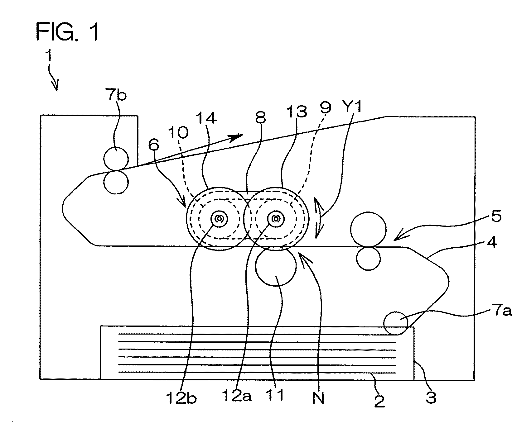
[0020]FIG. 1 is a schematic sectional view showing a schematic configuration of a printer 1 serving as an image forming apparatus comprising a fixing device 6 in the embodiment of the present invention. Referring to FIG. 1, the printer 1 comprises a cassette 3 containing paper 2, a paper feeding roller 7a for delivering the paper 2 to a paper conveying path 4 from the cassette 3, an image forming section 5 provided on the paper conveying path 4 for transferring a toner image on the paper 2, a fixing device 6 provided on the paper conveying path 4 for fixing the toner image that has been transferred on the paper 2, and a discharge roller 7b for discharging the paper 2 on which the toner image has been fixed from the printer.

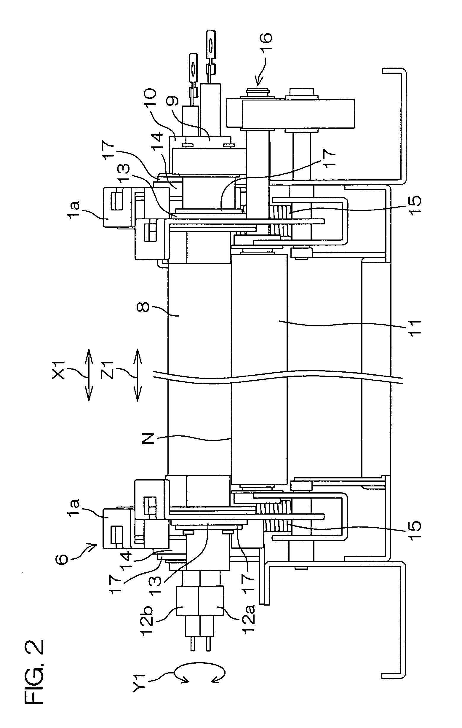
[0021]FIG. 2 is a front view of the fixing device 6 in an embodiment of the present invention, and FIG. 3 is a transverse sectional view of the fixing device 6 s...


PUM


Abstract

A fixing device 6 according to the present invention has an endless-shaped heating belt 8, a first and a second roller 9 and 10 for stretching the heating belt 8, and a pressure roller 11 for nipping paper 2, together with the heating belt 8. The first roller 9 is supported so as to be rotatable by bearings 13 arranged at both ends of the first roller 9. The second roller 10 is supported so as to be rotatable by bearings 14 arranged at both ends of the second roller 10. The bearing 13 for supporting the first roller 9 is arranged more inward in an axial direction Z1 of the rollers than the bearing 14 for supporting the second roller 10.

Description

BACKGROUND OF THE INVENTION[0001]1. Field of the Invention[0002]The present invention relates to a fixing device provided in an image forming apparatus such as a printer, a copying machine, or a facsimile.[0003]2. Description of Related Art[0004]Examples of a fixing device provided in an image forming apparatus include one comprising an endless-shaped heating belt and a pressure roller pressed against the heating belt. Paper on which a toner image has been transferred is nipped by the heating belt and the pressure roller, to be heated and pressurized. Thus, the toner image is fixed on the paper.[0005]The heating belt is stretched between a pair of rollers spaced a predetermined distance apart from and arranged parallel to each other in the direction of movement of the heating belt, as disclosed in Japanese Unexamined Patent Publication No. 2000-150112, for example. Each of the pair of rollers is supported so as to be rotatable by bearings arranged at both ends of the roller.[0006]In...

Claims


Application Information

Patent Timeline
Patent Type & Authority Applications(United States)
IPC IPC(8): G03G15/20
CPCG03G15/2053G03G2215/2032G03G2215/2016
Inventor ISHIDA, NAOYUKIKITAGAWA, HIDEKIKONDO, AKIHIRO
Owner KYOCERA DOCUMENT SOLUTIONS INC
Why Eureka
Try Eureka