Electrical connector

a technology of electrical connectors and coupling rings, applied in the direction of coupling device connections, coupling parts engagement/disengagement, electrical apparatus, etc., can solve the problems of coupling ring turning, coupling ring turning, and the amount of time required for connecting or disconnecting such a plug connection

Inactive Publication Date: 2009-07-02
CONINVERS
View PDF6 Cites 23 Cited by
  • Summary
  • Abstract
  • Description
  • Claims
  • Application Information

AI Technical Summary

Benefits of technology

[0006]The invention therefore addresses the problem of proposing an electrical connector where the turning of the coup

Problems solved by technology

A disadvantage of such known connectors with standard thread is the amount of time required for connecting or disconnecting such a plug connection.
It is consid

Method used


Image

  • Electrical connector
  • Electrical connector
  • Electrical connector

Examples


Embodiment Construction

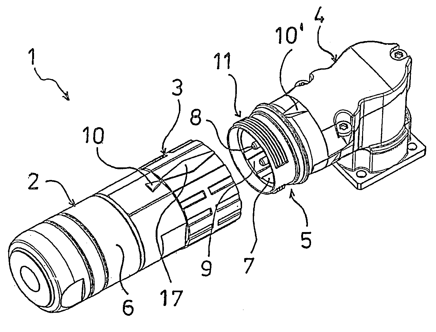
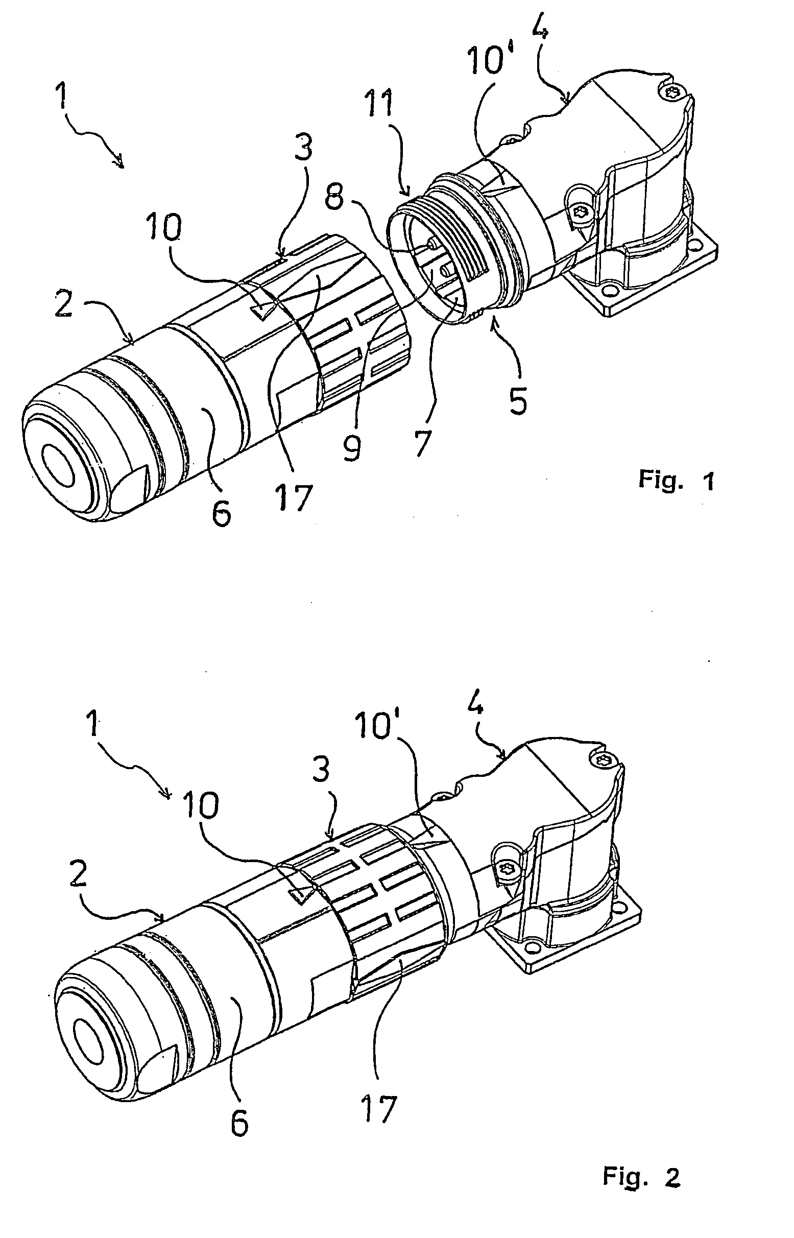
[0024]The electrical connector 1 according to the invention shown in FIG. 1, 2 comprises an oblong connector part 2 with a coupling ring 3 and a mating connector part 4 that has the form of an angle flange in this embodiment. The coupling ring 3 is rotatably fastened to the connector part 2 and serves to be screwed to a threaded sleeve 5 of the mating connector part 4. The connector part 2 can be plugged together with the mating connector part 4 exclusively in the position of the coupling ring 3 shown in FIG. 1 in relation to the body 6 of the connector part 2. In plugged-together condition, the connector part 2 and the mating connector part 4 can be locked together by rotating the coupling ring 3 by a maximum of 135 degrees.

[0025]The mating connector part 4 comprises a contact carrier 7 with contact elements 8 and a coding device 9 that are provided in a complementary manner on the connector part 2 but are not shown in the drawing. Connecting the connector part 2 with the mating co...


PUM


Abstract

The invention relates to an electrical connector, comprising a connector part and a mating connector part which can be plugged together, and a coupling ring, carried by the connector part, for screwing the connector part with a threaded sleeve of the mating connector part. An outer thread of the threaded sleeve and a correspondingly configured inner thread of the coupling ring have at least one unthreaded section each in the direction of insertion. The respective unthreaded and threaded sections are configured and arranged in such a manner that the threaded sections of the coupling ring and the threaded sleeve can be inserted into the respective unthreaded section of the other connector part in order to plug the connector and mating connector together. The connector according to the invention is characterized by at least one raised annular collar section in front of at least one unthreaded section of the coupling ring in the direction of insertion, said annular collar section allowing the coupling ring to be rotated, when the connector is plugged together, once the annular collar section has passed the unthreaded section of the thread of the threaded sleeve.

Description

TECHNICAL FIELD OF THE INVENTION[0001]The invention relates to an electrical connector, comprising a connector part and a mating connector part which can be plugged together, and a coupling ring, carried by the connector part, for screwing the connector part with a threaded sleeve of the mating connector part, according to the preamble of claim 1.DISCUSSION OF RELATED ART[0002]Such connectors are generally known and are preferably used for electrical connections that are to be connected and disconnected quickly and in a simple manner. After they are connected, the coupling ring secures the connector part and the mating connector part against unintended disconnection. For this purpose, the coupling ring that has an inner thread is commonly screwed onto a mating outer thread of the mating connector part until it reaches an axial stop, and is then tightened so that the screwed connection cannot come apart. A disadvantage of such known connectors with standard thread is the amount of ti...

Claims


Application Information

Patent Timeline
IPC IPC(8): H01R13/622
CPCH01R13/622H01R13/5219
Inventor SCHOLLER, JOHANNFREDL, SONJA
Owner CONINVERS
Why Eureka
Try Eureka