
High conductivity inductively equalized electrodes and methods

a technology of inductive equalization and electrodes, applied in the field of apparatus and methods for electrosurgery, can solve the problems of patient tissue damage, excessive heating, and burns on the patient's body at the location of the return electrod

Inactive Publication Date: 2009-07-02
CUTERA
View PDF16 Cites 7 Cited by
  • Summary
  • Abstract
  • Description
  • Claims
  • Application Information

AI Technical Summary

Benefits of technology

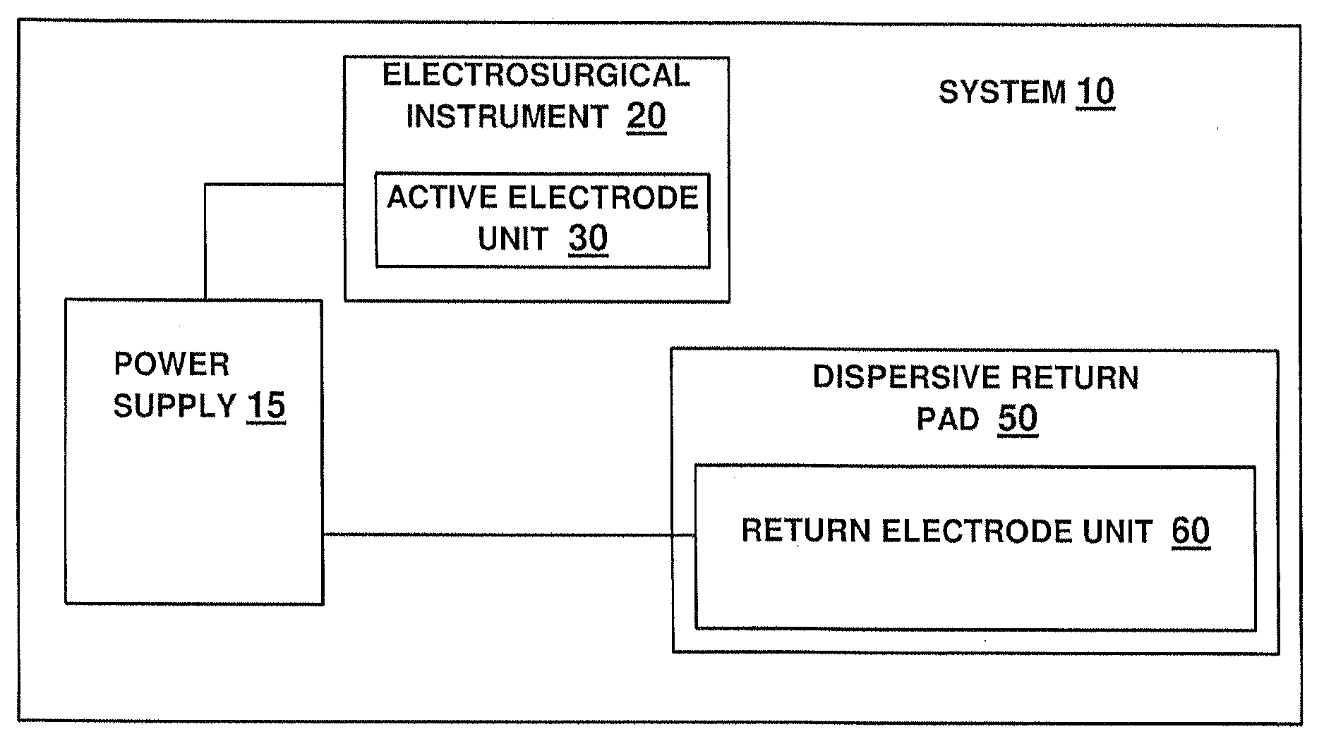
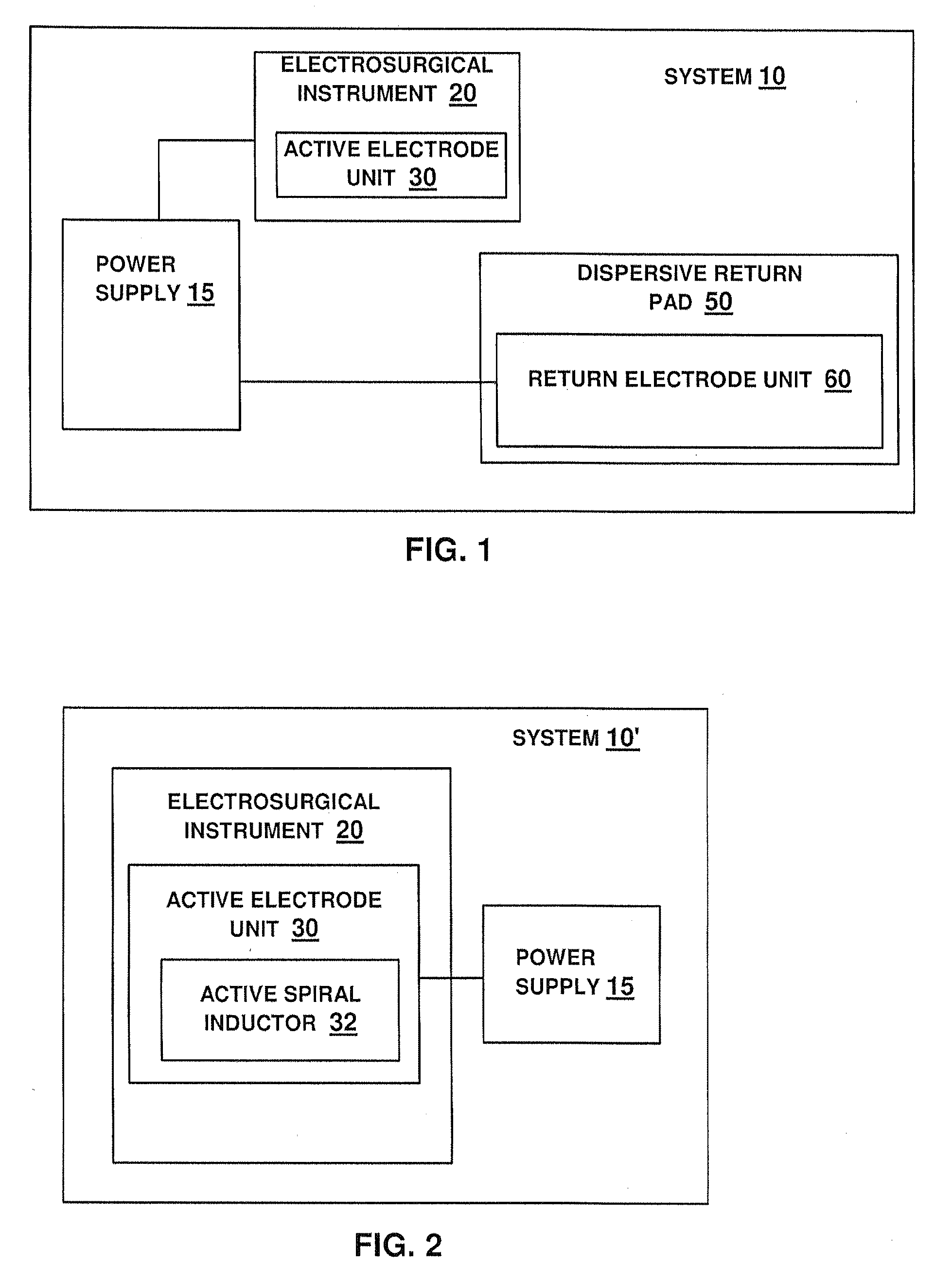
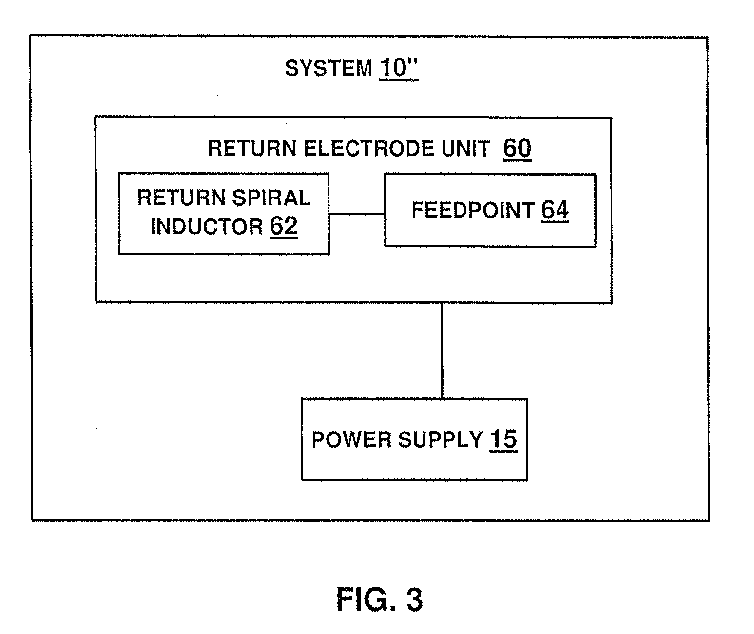
[0010]According to one aspect of the invention, there is provided apparatus comprising an electrosurgical instrument including an active electrode unit. The active electrode unit comprises at least one spiral inductor, each spiral inductor includes a spiral comprising an electrically conductive metal, and each spiral inductor is configured for applying electrical energy to a target tissue of the patient's body. According to another aspect of the invention, there is provided apparatus for receiving electrical energy from a patient. The apparatus comprises a d...

Problems solved by technology

A disadvantage of monopolar electrosurgery using prior art return electrodes is the risk of burns on the patient's body at the location of the return electrode.
Concentration, or uneven distribution, of electric current density at the return electrode surface may cause excessive heating to the extent that a severe burn to the patient's tissue can result.
However, with the increase in the number of dispersive pads, the correct placement becomes more difficult, while incorrect placement of the pads also increases the risk of a patient burn.
Increasing the number of dispersive pads may also complicate monitoring of dispersive pad contact with the patient.
A similar disadvantage of monopolar electrosurgery, using prior art active electrodes for treating a target tissue, is uneven electric current density distribution over the surface of the active electrode, e.g., current density may be concentrated at the corners and / or edges of the active electrode.
Such uneven distribution of electric current density over the active electrode surface may lead to uneven heating or treatment of the patient's tissue with undesirable effects on the patient.

Method used


Image

  • High conductivity inductively equalized electrodes and methods
  • High conductivity inductively equalized electrodes and methods
  • High conductivity inductively equalized electrodes and methods

Examples


Embodiment Construction

[0045]The following detailed description is of the best currently contemplated modes of carrying out the invention. The description is not to be taken in a limiting sense, but is made merely for the purpose of illustrating the general principles of the invention, since the scope of the invention is best defined by the appended claims.

[0046]Broadly, the present invention provides methods and apparatus for performing monopolar electrosurgical procedures in a safe and effective manner while preventing the uneven treatment of a target tissue and / or patient burns. Patient burns are known to occur using apparatus and methods of the prior art due to uneven distribution of electric current density over the surface of conventional return electrodes. In contrast to prior art devices, return electrode units of the instant invention are configured for evenly distributing electric current density thereover, thereby preventing patient burns. The present invention may also permit higher total curr...


PUM


Abstract

Apparatus and methods for evenly distributing electric current density over a surface of at least one of an active electrode and a return electrode during electrosurgery, wherein the active and / or return electrode includes a spiral inductor. The spiral inductor may include a low electrical resistivity material or a spiral bare metal surface for contacting the patient's body. In a multi-layer spiral inductor having a plurality of stacked spirals, each turn of a first spiral may be electrically coupled in series to a radially corresponding turn of each successive one of the stacked spirals; and each turn of the innermost spiral may be electrically coupled to an adjacent, radially outward turn of the outermost spiral.

Description

FIELD OF THE INVENTION[0001]The present invention generally relates to apparatus and methods for electrosurgery.BACKGROUND OF THE INVENTION[0002]Various forms of electrosurgery are now widely used for a vast range of surgical procedures. There are two basic forms or electrosurgery, namely monopolar and bipolar, according to the configuration of the electrosurgical system which determines the path of electrical energy flow vis-à-vis the patient. In the bipolar configuration, both the active electrode and the return electrode are located adjacent to a target tissue of the patient, i.e., the electrodes are in close proximity to each other, and current flows between the electrodes locally at the surgical site.[0003]In monopolar electrosurgery, the active electrode is again located at the surgical site; however, the return electrode, which is typically much larger than the active electrode, is placed in contact with the patient at a location on the patient's body that is remote from the ...

Claims


Application Information

Patent Timeline
IPC IPC(8): A61B18/14
CPCA61B2018/1437A61B18/16
Inventor LEYH, GREG
Owner CUTERA
Learn More