Flowmeter

a flowmeter and flow rate technology, applied in the direction of liquid/fluent solid measurement, volume metering, instruments, etc., can solve the problems of increasing difficulty, reducing the accuracy of coating, and reducing the possibility of elution of metal ions into fluid pipes, so as to reduce the deterioration of measurement accuracy with lapse of time, the change in the elastic modulus by temperature or the creep phenomenon can be greatly reduced

Inactive Publication Date: 2009-07-09
KEYENCE
View PDF7 Cites 17 Cited by
  • Summary
  • Abstract
  • Description
  • Claims
  • Application Information

AI Technical Summary

Benefits of technology

[0016]Also, since the outer pipe having a larger elastic modulus is made of what is known as a fiber reinforced plastics in which the resin is cured in close adhesion between the fibers, the rigidity of the fluid pipe increases in an outstanding manner as compared with a pipe made of fluororesin. Moreover, since it

Problems solved by technology

S64-15921, when the pipe diameter is small, the coating is difficult, and in particular, when there is a bent portion, a degree of difficulty is increased.
Also, as another requirement, there is a requirement that no metal is used at all as a material of the pipe because a fluororesin coating has a difficulty in increasing the film thickness and also it is difficult to confirm whether the coating has been done with certainty, whereby the fear of elution of the met

Method used


Image

  • Flowmeter
  • Flowmeter
  • Flowmeter

Examples


example 1

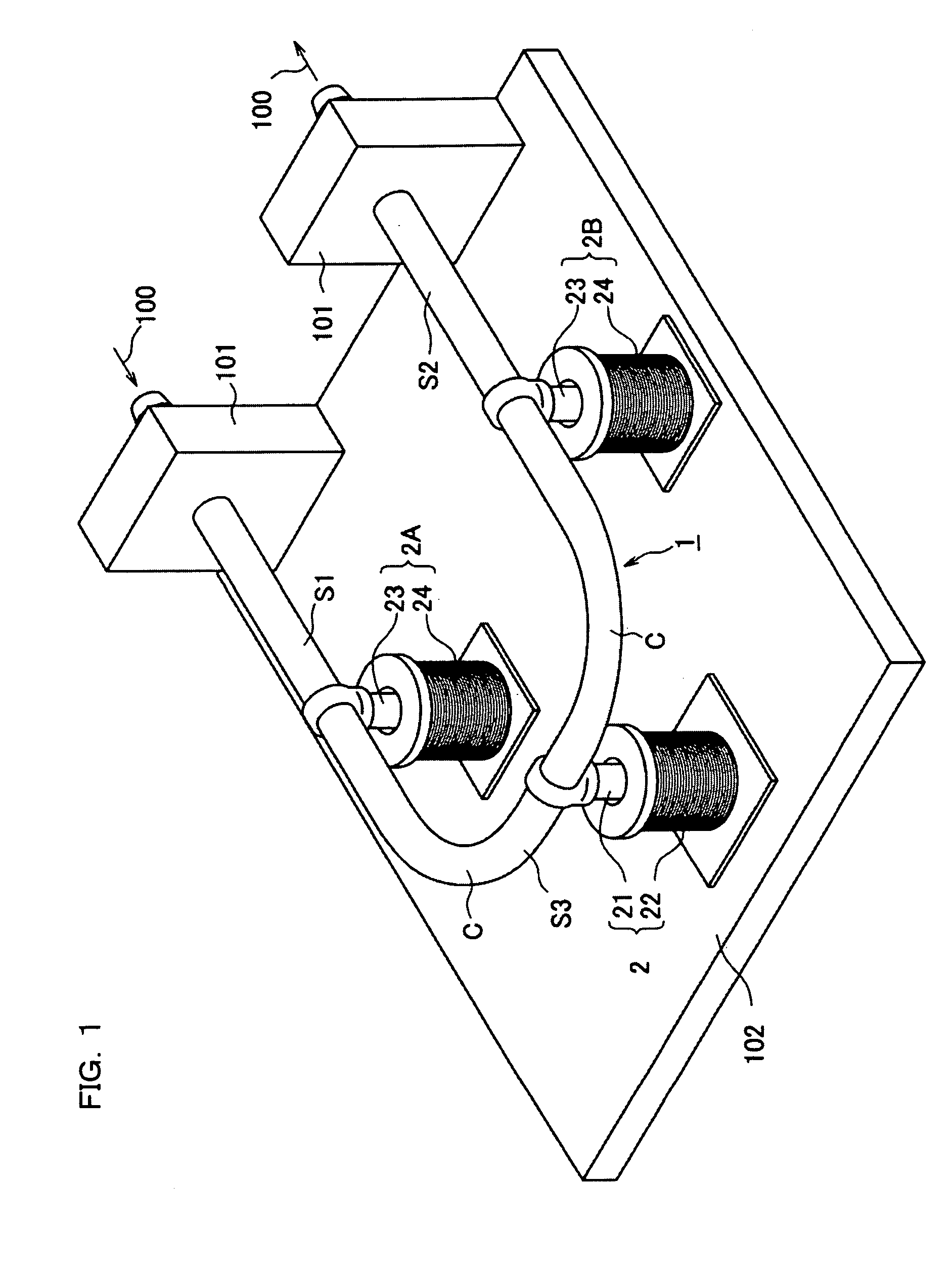
[0058]Hereafter, Example 1 of the present invention will be described with reference to FIGS. 1 to 7. Prior to the description of the essential parts of the present invention, the structure, the principle, and the like of a Coriolis mass flowmeter will be described.

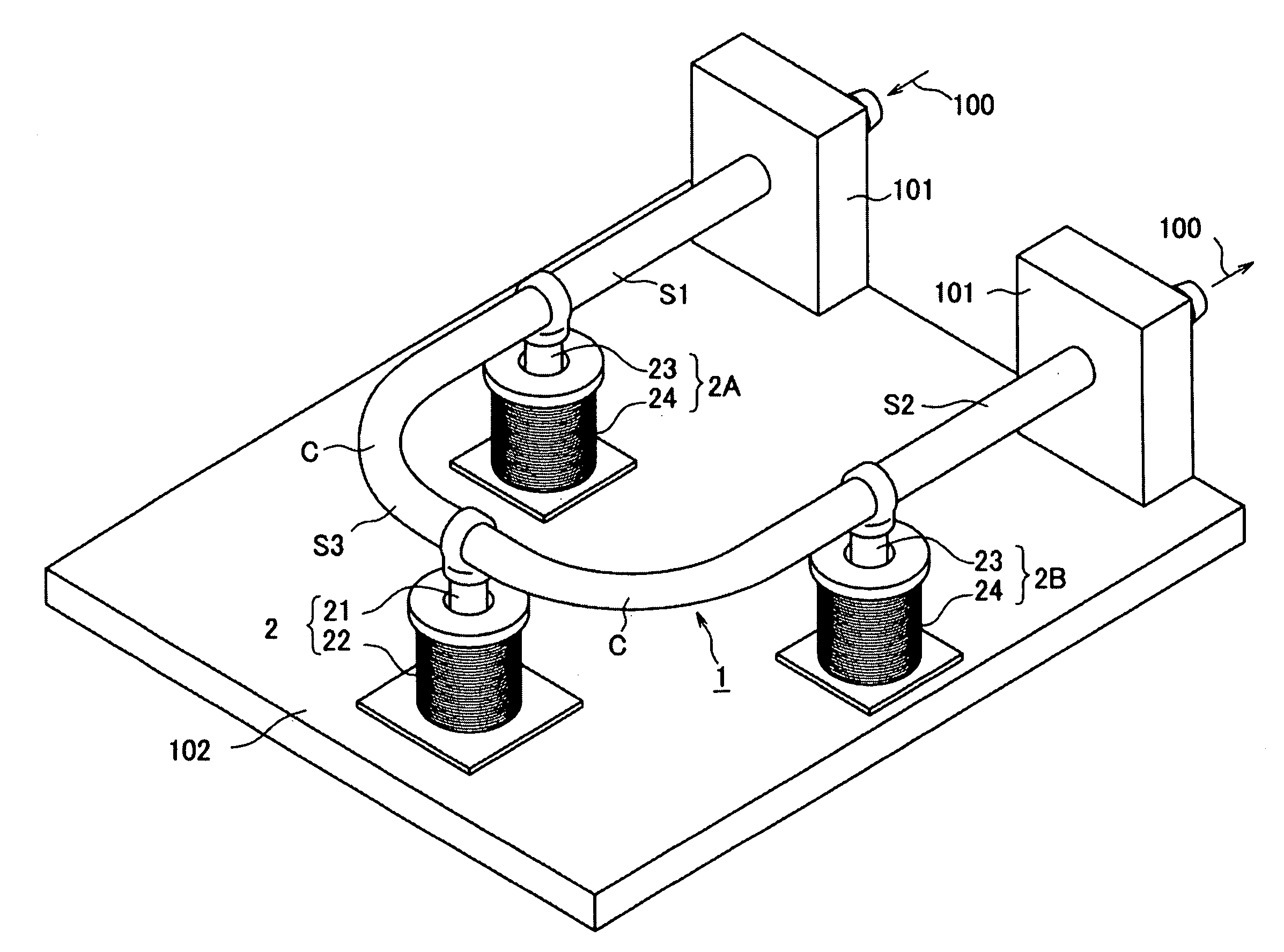
[0059]In FIG. 1, an approximately U-shaped fluid pipe 1 has first to third straight pipe portions S1 to S3 and two bent portions C, thereby to form a flow path 10 of a measurement fluid 100 serving as an object of measurement (FIG. 4). The measurement fluid 100 is introduced from the first straight pipe portion S1 of the fluid pipe 1 and passes through the bent portion C, the third straight pipe portion S3, and the bent portion C to be guided to the outside from the second straight pipe portion S2.

[0060]The ends of the first and second straight pipe portions S1, S2, that is, the two ends of the approximately U-shaped fluid pipe 1 are fixed to a wall portion 101. When this is viewed from the viewpoint of structural mechani...

example 2

[0085]FIGS. 9A to 9D show Example 2 of the present invention.

[0086]In the above Example 1, all of the bent portion C and the straight pipe portions S1 to S3 of the U-shaped fluid pipe 1 are formed with the inner pipe 11 and the outer pipe 12. In the present Example, the straight pipe portions S1 to S3 are formed with the inner pipe 11 and the outer pipe 12, and the bent portion C is formed with the inner pipe 11.

[0087]In this case, the bent portion C may be formed only with the inner pipe 11; however, the bent portion C may be covered with an epoxy resin or the like not having the fibers F1, F2. By covering with the epoxy resin or the like, the rigidity and the chemical resistance of the fluid pipe 1 are improved.

[0088]Further, regarding the fibers of the straight pipe portions S1 to S3, the fibers F1, F2 may be oriented in two spiral directions as shown in FIG. 9B, or only the fibers F1 may be arranged in order and oriented only in one spiral direction as shown in FIG. 9C.

[0089]Fur...

example 3

[0090]FIG. 10 shows Example 3 of the present invention.

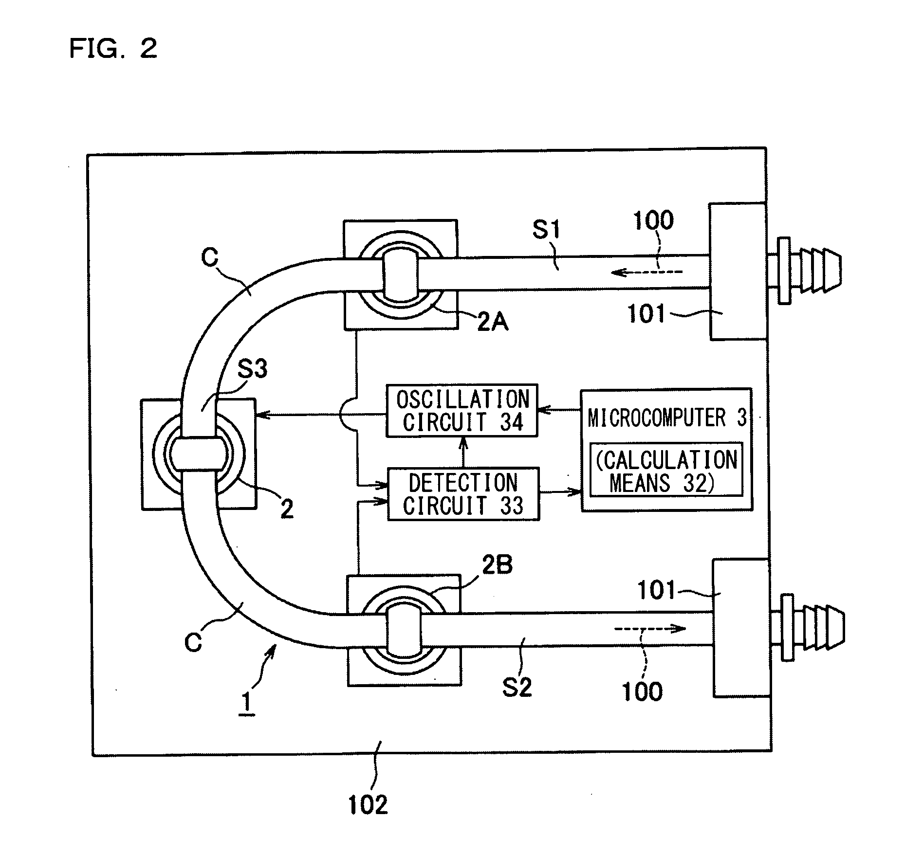
[0091]In the above Examples 1 and 2, the bent portion C is included between the two detectors 2A and 2B as shown in FIG. 1; however, the bent portion C may be absent between the two detectors 2A and 2B as shown in FIG. 10.

[0092]Herein, in each of the above-described Examples, a case having two layers has been described; however, the fluid pipe may be made of three or more layers.

[0093]For example, the outside of the outer pipe 12 of FIG. 4 may be covered with another resin or the like, so as to improve the adhesiveness or the outer appearance, or to enhance the fixing force of the elements to be detected.

[0094]On the other hand, another resin or the like may be inserted between the inner pipe 11 and the outer pipe 12 of FIG. 4. For example, in order to improve the adhesiveness of the inner pipe 11 and the outer pipe 12, an underlying material (primer) having an affinity to both of the inner pipe 11 and the outer pipe 12 may be i...


PUM


Abstract

A Coriolis flowmeter includes an oscillator for oscillating a fluid pipe that forms a flow path for allowing a measurement fluid to flow; first and second detectors that are disposed to be spaced apart from each other along the flow path of the fluid pipe so as to detect a state of oscillation of the fluid pipe; and a calculator for calculating a mass flow rate of the measurement fluid that passes through the flow path of the fluid pipe on the basis of a relative amount of the states of oscillation that are detected by the first and second detectors. The fluid pipe includes an inner pipe made of a fluororesin whose inner circumferential surface is in contact with the flow path, and an outer pipe having fibers that are arranged in order to surround an outer circumferential surface of the inner pipe and a resin that is cured in a state of close adhesion between the fibers arranged in order, and having an elastic modulus larger than that of the inner pipe.

Description

CROSS-REFERENCE TO RELATED APPLICATIONS[0001]The present application claims foreign priority based on Japanese Patent Application No. 2008-000318, filed Jan. 7, 2008, the contents of which is incorporated herein by reference.BACKGROUND OF THE INVENTION[0002]1. Field of the Invention[0003]The present invention relates to a Coriolis mass flowmeter that generates a Coriolis force, i.e. a force that acts in proportion to the mass flow rate of a fluid flowing through a pipe by forcibly oscillating the pipe and detecting the phase difference of the oscillations on the upstream side and the downstream side of the pipe to determine a mass flow rate.[0004]2. Description of the Related Art[0005]A Coriolis flowmeter forcibly oscillates with an oscillator a fluid pipe that passes a fluid as an object of measurement, and detects the phase difference of the oscillations that is generated on the upstream side and the downstream side of the flow path in accordance with the flow rate of the mass of ...

Claims


Application Information

Patent Timeline
IPC IPC(8): G01F1/20
CPCG01F1/8413G01F15/006G01F1/8472
Inventor TAKAYANAGI, SUSUMU
Owner KEYENCE
Why Eureka
Try Eureka