Chain drive system

a chain drive and drive shaft technology, applied in the direction of gearing details, belts/chains/gearrings, gearing details, etc., can solve the problems of high production cost, high overall cost, and limited production location and amount of special equipment, so as to reduce the overall production cost of the chain drive system, reduce the amount of use of an expensive material, and reduce the sliding resistance

Active Publication Date: 2020-04-28
TSUBAKIMOTO CHAIN CO
View PDF16 Cites 0 Cited by
  • Summary
  • Abstract
  • Description
  • Claims
  • Application Information

AI Technical Summary

Benefits of technology

[0012]Another problem was that when PTFE particles come off of the surface of the guide shoe as the chain slides on the guide shoe, the sliding resistance is increased. The sliding surface of the guide shoe grows irregular as the PTFE particles come off, which further increases the sliding resistance.
[0022]According to the configuration as set forth in claim 6, the matrix has a larger elastic modulus than the additive, a lower melting point than the additive, a larger friction coefficient than the additive, a smaller impact resistance than the additive, and a larger mold shrinkage rate than the additive. Therefore, solid lubricant particles largely exposed on the surface of the chain running surface can readily come off. An increase in sliding resistance because of the surface irregularities of the chain running surface after the particle detachment is minimal. Further, detachment of remaining solid lubricant thereafter is minimized.

Problems solved by technology

PTFE-added nylon resin such as the one shown in Japanese Patent Application Laid-open No. 2007-177037 is hard to produce and the production cost is high because of the use of PTFE that is produced by modifying PTFE powder under a special environment.
Also, the need to use special equipment poses limitations on the location and amount of production.
Therefore, when an expensive material such as the one shown in Japanese Patent Application Laid-open No. 2007-177037 is applied for the guide shoes of the timing system of a car engine or the like, the overall cost becomes very high.

Method used


Image

  • Chain drive system
  • Chain drive system
  • Chain drive system

Examples


embodiment

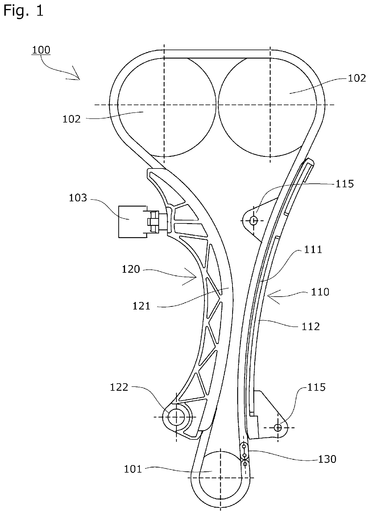
[0029]A chain drive system 100 according to a first embodiment of the present invention will be described with reference to the drawings.

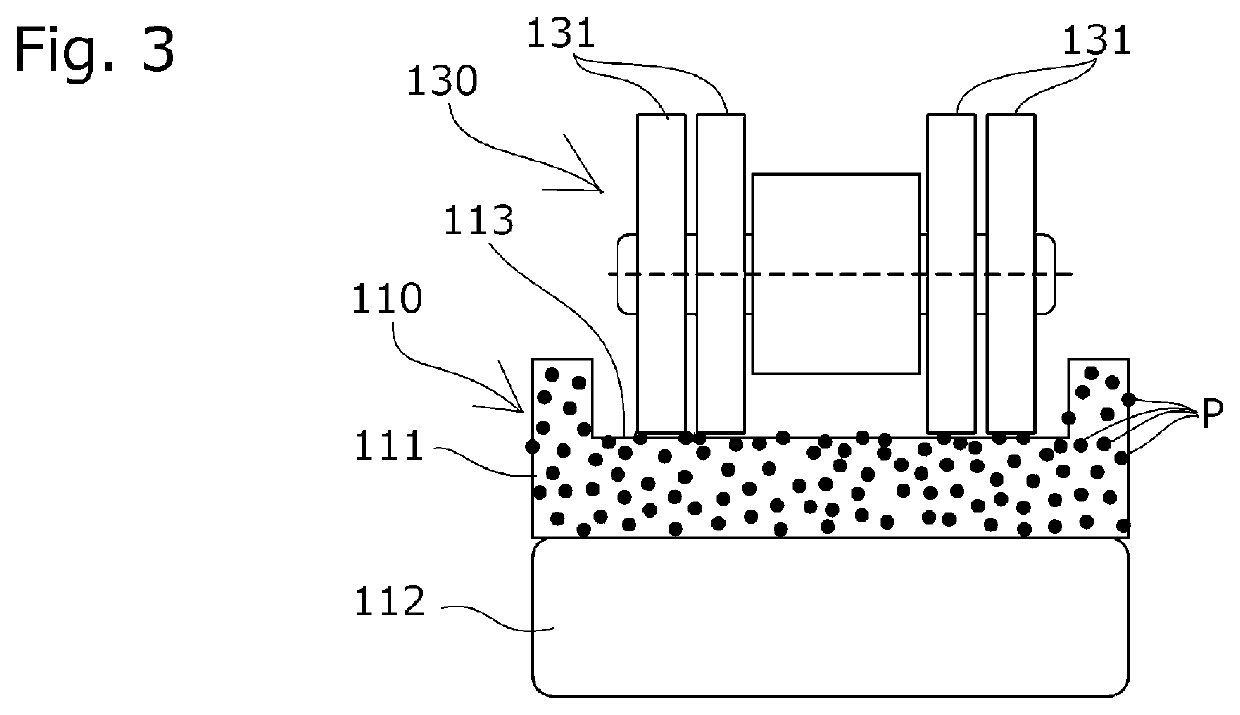
[0030]The chain drive system 100 is applied to a timing system of a car engine. As shown in FIG. 1, a chain 130 such as a roller chain passes over a drive sprocket 101 provided to a crankshaft and two driven sprockets 102 provided to two respective camshafts. The chain 130 running between the drive sprocket 101 and the driven sprockets 102 is guided by a fixed guide 110 and a pivot lever guide 120.

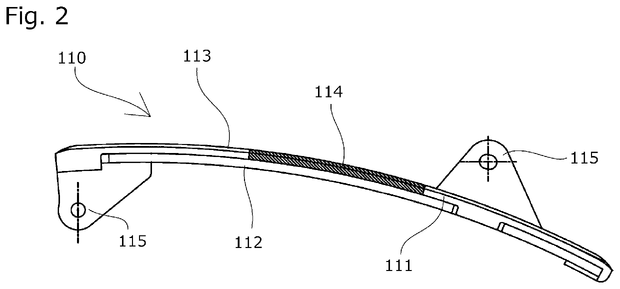
[0031]The fixed guide 110 includes a guide shoe 111 that has a chain running surface 113 for slidably guiding the running chain, and a base member 112 that supports the guide shoe 111 along the chain running direction. An attachment portion 115 extending from the base member 112 is secured to the engine.

[0032]The pivot lever guide 120 is formed integral with a guide shoe 121 that slidably guides the running chain and pivotally attached to the engine at a ...


PUM


Abstract

An object of the present invention is to provide a chain drive system that can reduce sliding resistance between a chain and a guide shoe, minimize increase of sliding resistance over time, and reduce production cost. Provided is a chain drive system 100 including a plurality of sprockets 101 and 102 over which a chain 130 passes over, and one or more guides 110 and 120 that guide the chain 130. The guides 110 and 120 include integral or separate guide shoes 111 and 121 each having a chain running surface. The chain running surfaces include, in part thereof, a lubricated area 114 where a solid lubricant P is held.

Description

BACKGROUND OF THE INVENTION1. Field of the Invention[0001]The present invention relates to a chain drive system that includes a plurality of sprockets over which a chain passes over and one or more guides for slidably guiding the chain, the guide having an integral or separate guide shoe that has a chain running surface.2. Description of the Related Art[0002]Chain drive systems having a guide that guides a running chain and includes an integral or separate guide shoe having a chain running surface for slidably guiding the chain are commonly used to stabilize the chain running between sprockets and to keep an appropriate tension.[0003]It is very desirable that the sliding resistance between the chain and the chain running surface of the guide shoe be small from the viewpoints of noise reduction and drive power loss reduction.[0004]Various measures have been taken such as selecting materials and shapes of the chain and guide shoe, and applying surface treatment and lubricant, etc.[000...

Claims


Application Information

Patent Timeline
Patent Type & Authority Patents(United States)
IPC IPC(8): F16H7/06F16H57/05F16H7/08F16H7/18
CPCF16H57/05F16H7/18F16H7/06F16H2007/0872F16H2007/185F16H2007/0893F16H2007/0874
Inventor KONNO, MASAHIKOMORI, KAORISEGAWA, RYO
Owner TSUBAKIMOTO CHAIN CO
Why Eureka
Try Eureka