Method For Controlling A Wind Turbine Connected To The Utility Grid, Wind Turbine And Wind Park

a technology of wind power generator and utility grid, which is applied in the direction of electric generator control, machines/engines, mechanical equipment, etc., can solve the problems of incompatibility of said prior art method and grid codes, inflicting wind power generator breakdown, and increasing the speed of generators almost immediately

Inactive Publication Date: 2009-07-09
VESTAS WIND SYST AS
View PDF47 Cites 31 Cited by
  • Summary
  • Abstract
  • Description
  • Claims
  • Application Information

AI Technical Summary

Benefits of technology

[0015]In one aspect of the invention initiating said fault mode comprises establishing a value of the generated power by the wind turbine and entering said fault mode when the power is above a pre-established limit e.g. 25% of nominal power. Hereby it is ensured that said fault mode will not be initiated when the normal control algorithm will be able to avoid over speeding of the rotor during a grid fault event and will continue operating in normal mode since there is no imminent danger due to the low power in the wind.
[0032]The invention also relates to a wind park comprising at least two wind turbines according to any of the wind turbine claims and at least one detector for detecting failures in the utility grid. Hereby it is ensured that the wind park may actively assist the utility grid during the fault situation or at least not add to the severity of the situation.

Problems solved by technology

When a wind turbine experience a utility grid fault the generator speed increases almost immediately as a result of the excessive aerodynamical power that cannot be converted to electrical power.
But as the grid codes typically sets up requirements for a low voltage ride through (LVRT) that requires the wind turbine generator to stay connected, said method of prior art is not compatible with the grid codes.
A problem with the system during a persisting grid fault is that the wind turbine would continue to test the speed trip limit e.g. with the risk of inflicting a wind turbine break down.

Method used


Image

  • Method For Controlling A Wind Turbine Connected To The Utility Grid, Wind Turbine And Wind Park
  • Method For Controlling A Wind Turbine Connected To The Utility Grid, Wind Turbine And Wind Park
  • Method For Controlling A Wind Turbine Connected To The Utility Grid, Wind Turbine And Wind Park

Examples


Embodiment Construction

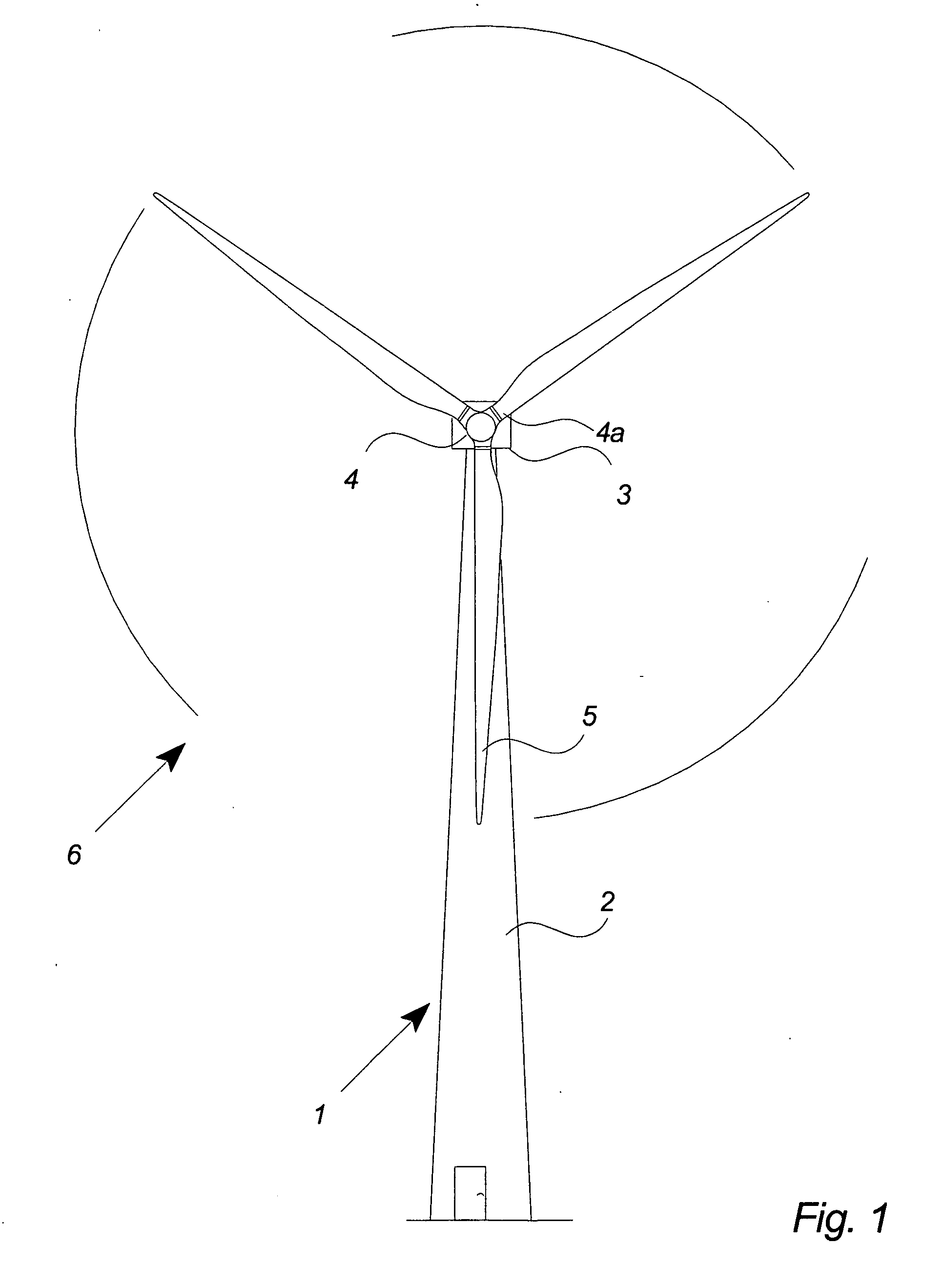
[0041]FIG. 1 illustrates a modern wind turbine 1 with a tower 2 and a wind turbine nacelle 3 positioned on top of the tower.

[0042]The wind turbine rotor, comprising at least one blade such as three wind turbine blades 5 as illustrated, is connected to the hub 4 through pitch mechanisms 4a. Each pitch mechanism includes a blade bearing and pitch actuating means which allows the blade to pitch. The pitch process is controlled by a pitch controller.

[0043]As illustrated in the figure, wind over a certain level will activate the rotor and allow it to rotate in a perpendicular direction to the wind. The rotation movement is converted to electric power which usually is supplied to the utility grid as will be known by skilled persons within the area.

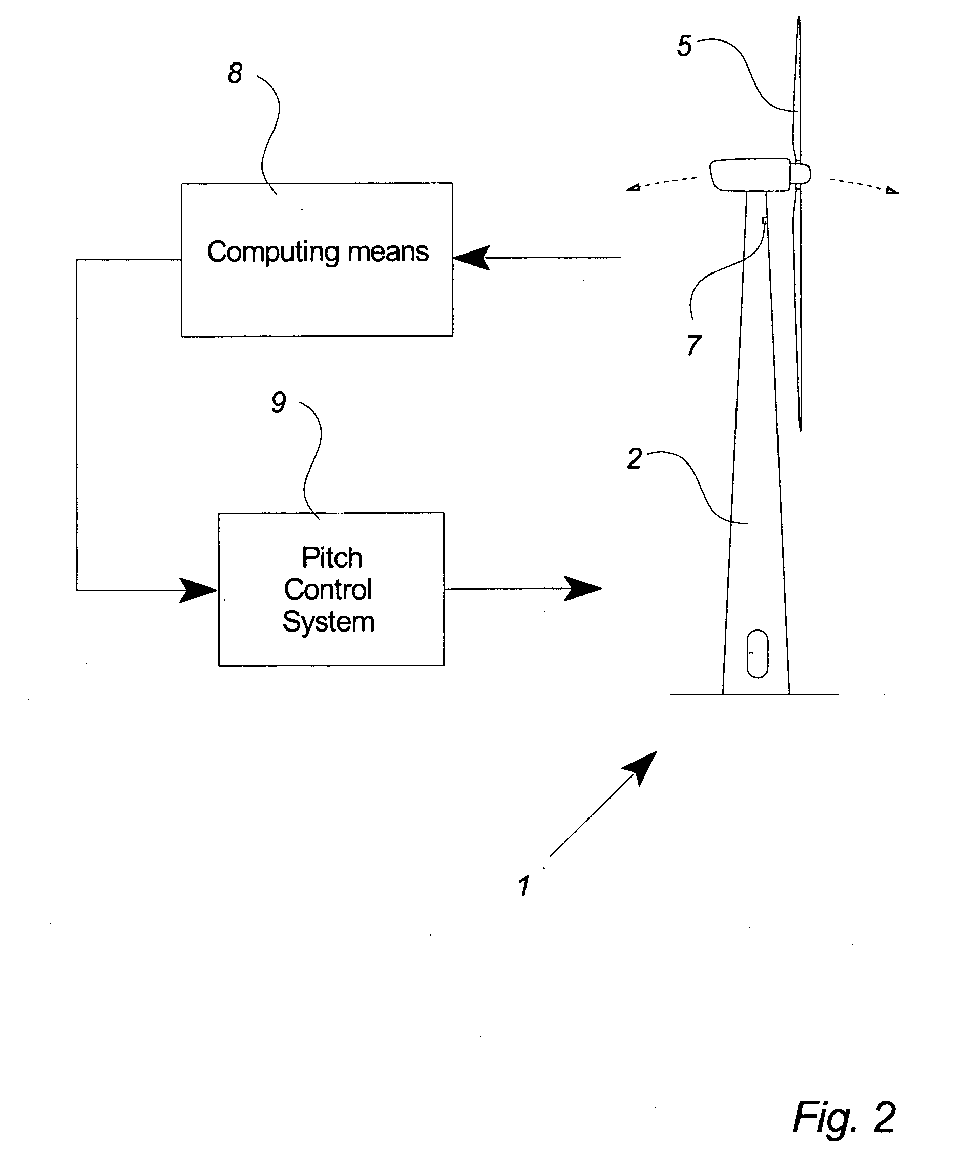
[0044]FIG. 2 illustrates schematically one preferred embodiment of a wind turbine with a control system, or controller, for controlling the pitch angles of the wind turbine blades.

[0045]Data of the wind turbine 1 are measured with sensor means 7...


PUM


Abstract

The invention relates to a method for controlling a wind turbine connected to the utility grid comprising steps of detecting a fault of the utility grid, and controlling one or more rotor blades in a fault mode wherein said one or more rotor blades are pitched in order to stabilize the rotor speed within an over speed range. The invention also relates to a wind turbine and a wind park comprising at least two wind turbines.

Description

CROSS-REFERENCE TO RELATED APPLICATIONS[0001]The present application is a continuation of pending International patent application PCT / DK2007 / 000405 filed on Sep. 12, 2007 which designates the United States and claims priority from Danish patent application PA 2006 01184 filed on Sep. 14, 2006, the content of which is incorporated herein by reference.FIELD OF THE INVENTION[0002]The invention relates to a method for controlling a wind turbine connected to the utility grid, a wind turbine and a wind park.BACKGROUND OF THE INVENTION[0003]National utility grid companies sets out the strategies and requirements for the connection of power generation equipment to the utility grid. These connection requirements are detailed described in Grid Codes and varies from nation to nation.[0004]One of the topics discussed in the grid codes is the capabilities of a wind turbine when the utility grid experiences a fault. It is essential for the operation of a wind turbine and for a reliable supply of...

Claims


Application Information

Patent Timeline
Patent Type & Authority Applications(United States)
IPC IPC(8): H02P9/04
CPCF03D7/0224F03D9/003Y02E10/723F05B2270/1011F05B2260/80F03D9/255Y02E10/72
Inventor NYBORG, ANDERS
Owner VESTAS WIND SYST AS
Why Eureka
Try Eureka