Device Support

Inactive Publication Date: 2009-07-09
BSW ANLAGENBAU
View PDF12 Cites 14 Cited by
  • Summary
  • Abstract
  • Description
  • Claims
  • Application Information

AI Technical Summary

Benefits of technology

[0003]It is, therefore, the objective of the present invention to improve a device support with a cabinet frame of

Problems solved by technology

However, the profiles are designed as open profiles that have relatively low torsion stiffness.
To make the screw heads accessible, the profiles are even disengaged at an angle at two adjacent a

Method used


Image

  • Device Support
  • Device Support
  • Device Support

Examples


Embodiment Construction

[0024]The preferred embodiments of the present invention will now be described with reference to FIGS. 1-6 of the drawings. Identical elements in the various figures are designated with the same reference numerals.

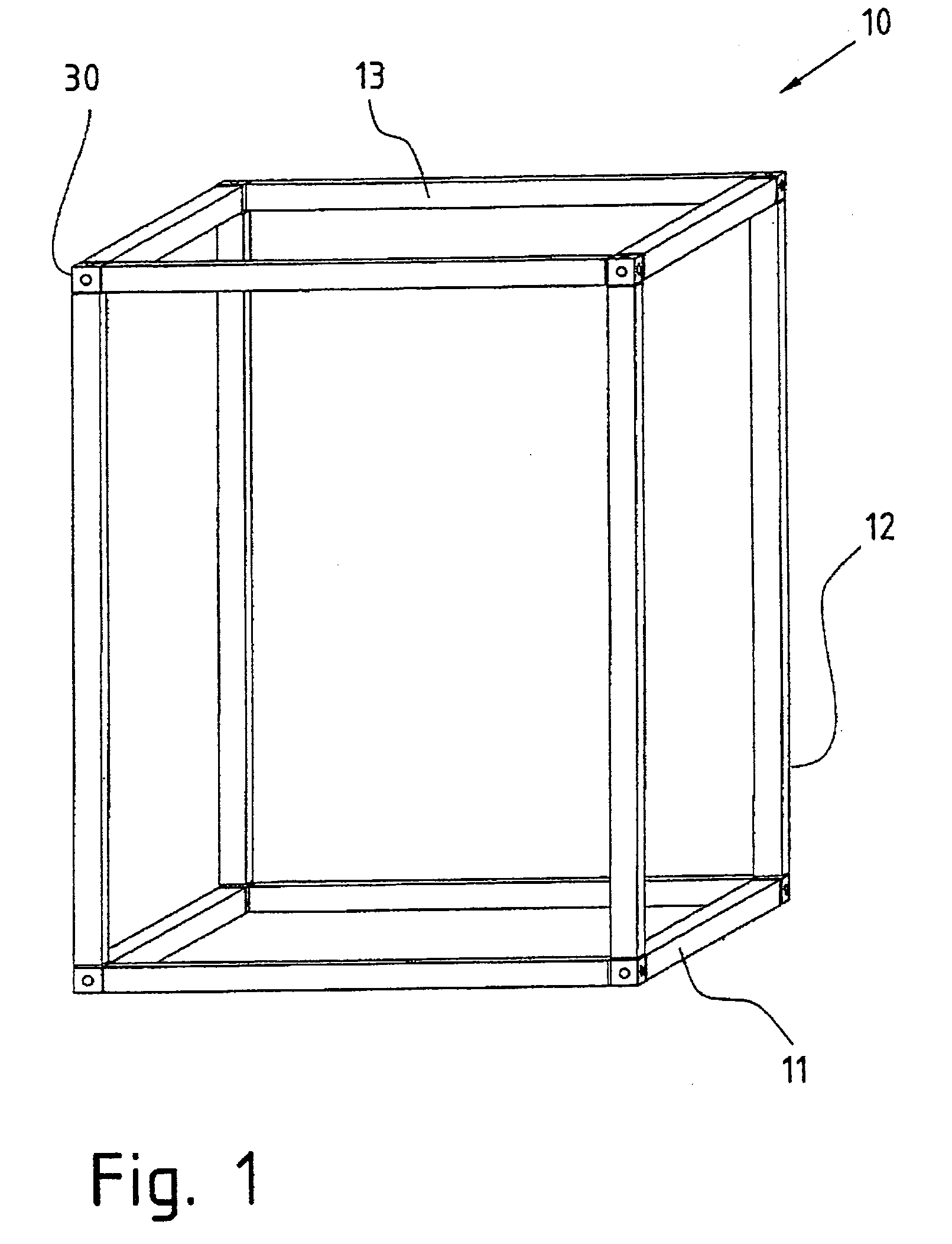
[0025]FIG. 1 shows a first cabinet frame 10 for a device support with hollow profiles 11, 12, 13 subject to the invention as well as corner connector elements 30. The cabinet frame includes a total of eight corner connector elements 30 as well as twelve hollow profiles. The corner connector elements 30 are connected with the profiles via screw connections. Because a spatial structure is being formed, the device support will be called a device cabinet hereafter.

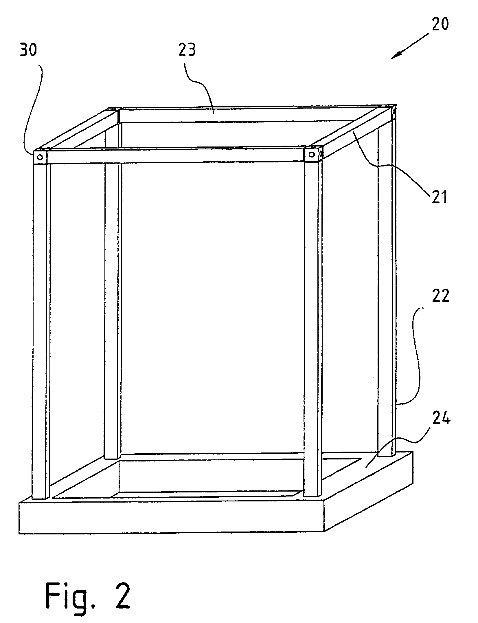
[0026]FIG. 2 shows a second cuboidal cabinet frame 20 with a rectangular base frame 24, where the four corners are each connected with a vertically arranged hollow profile 22 of the cuboidal cabinet frame 20 via a weld or screw connection. Corner connector elements 30 are arranged at the four upper corners of the cub...


PUM


Abstract

A device support comprises a cabinet frame that is formed by metal hollow profiles (11) and that has at least in one of its corners a parallelepiped corner connector element (30) connected to at least one of the hollow profiles (11) by means of a screw. At least one outside face of the corner connector element (30) is configured as a securing face which has a guiding shoulder (34) with at least two parallel outer edges (34.1), resting on inner peripheral surfaces of the hollow profile (11). The hollow profiles (11) have a closed cross-section. A throughbore runs from every securing face for receiving the screw shank and continues, starting from a support shoulder in the interior of the corner connection element (30), along a passage recess (32) which extends to an outside face of the corner connector element opposite the securing face.

Description

BACKGROUND OF THE INVENTION[0001]The present invention relates to a device support that includes a cuboidal cabinet frame formed by a metal hollow profile, which exhibits at least at one of its corners a cuboidal corner connector element that is connected to at least one of the hollow profiles via a screw connection, whereby at least one outer side of the corner connector element is designed as an attachment side that exhibits at least one guiding shoulder with at least two parallel outer edges that rest on inner perimetral surfaces of the hollow profile.[0002]Such a cabinet frame for a device support is known from the International Patent Application No. PCT / WO94 / 14307. The connection of corner connector elements and hollow profiles via screws allows for a modular design and requires significantly less storage and handling space when compared to welding structures that cannot be disassembled. However, the profiles are designed as open profiles that have relatively low torsion stiff...

Claims


Application Information

Patent Timeline
IPC IPC(8): E04B1/19A47B96/06
CPCH02B1/01Y10T403/342H02B1/014H02B1/013F16B12/44
Inventor NIENTIEDT, KLAUSZUTELGTE, ALBERT LUETKE
Owner BSW ANLAGENBAU
Why Eureka
Try Eureka