
Power selection system for air conditioner

Inactive Publication Date: 2009-07-16
YEH MING HSIANG
View PDF9 Cites 8 Cited by
  • Summary
  • Abstract
  • Description
  • Claims
  • Application Information

AI Technical Summary

Benefits of technology

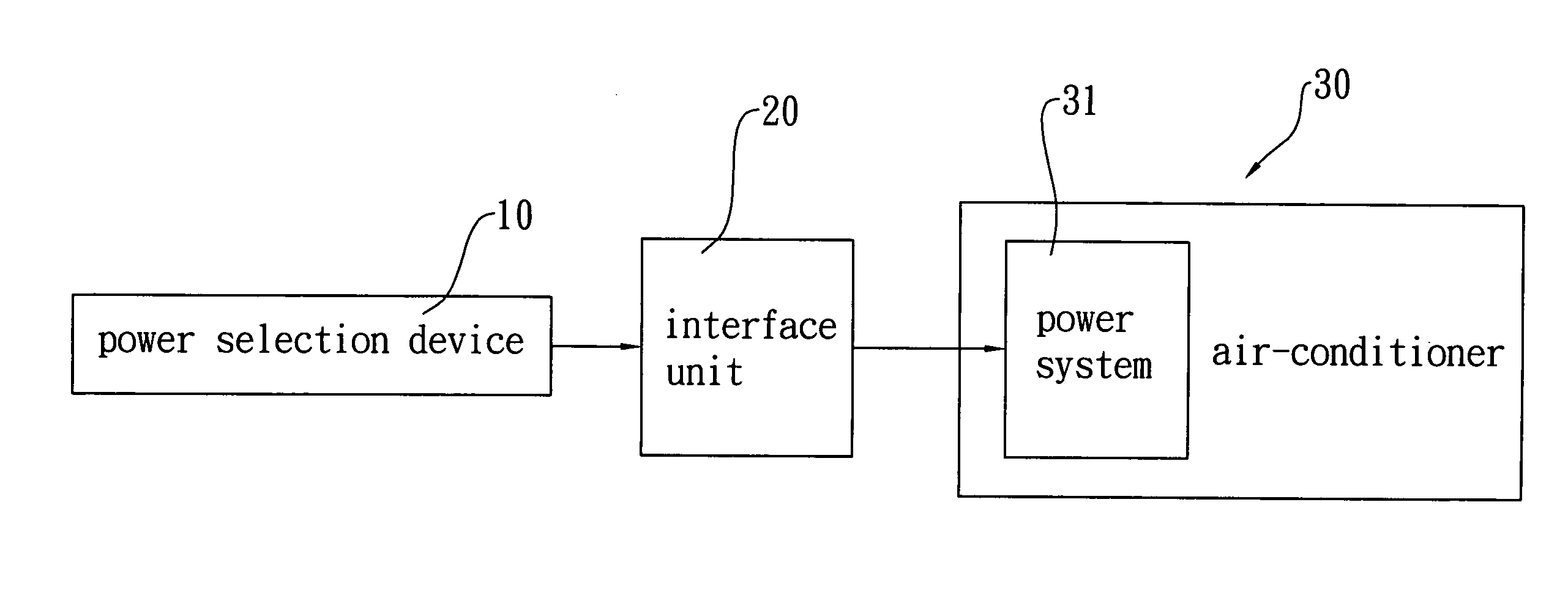
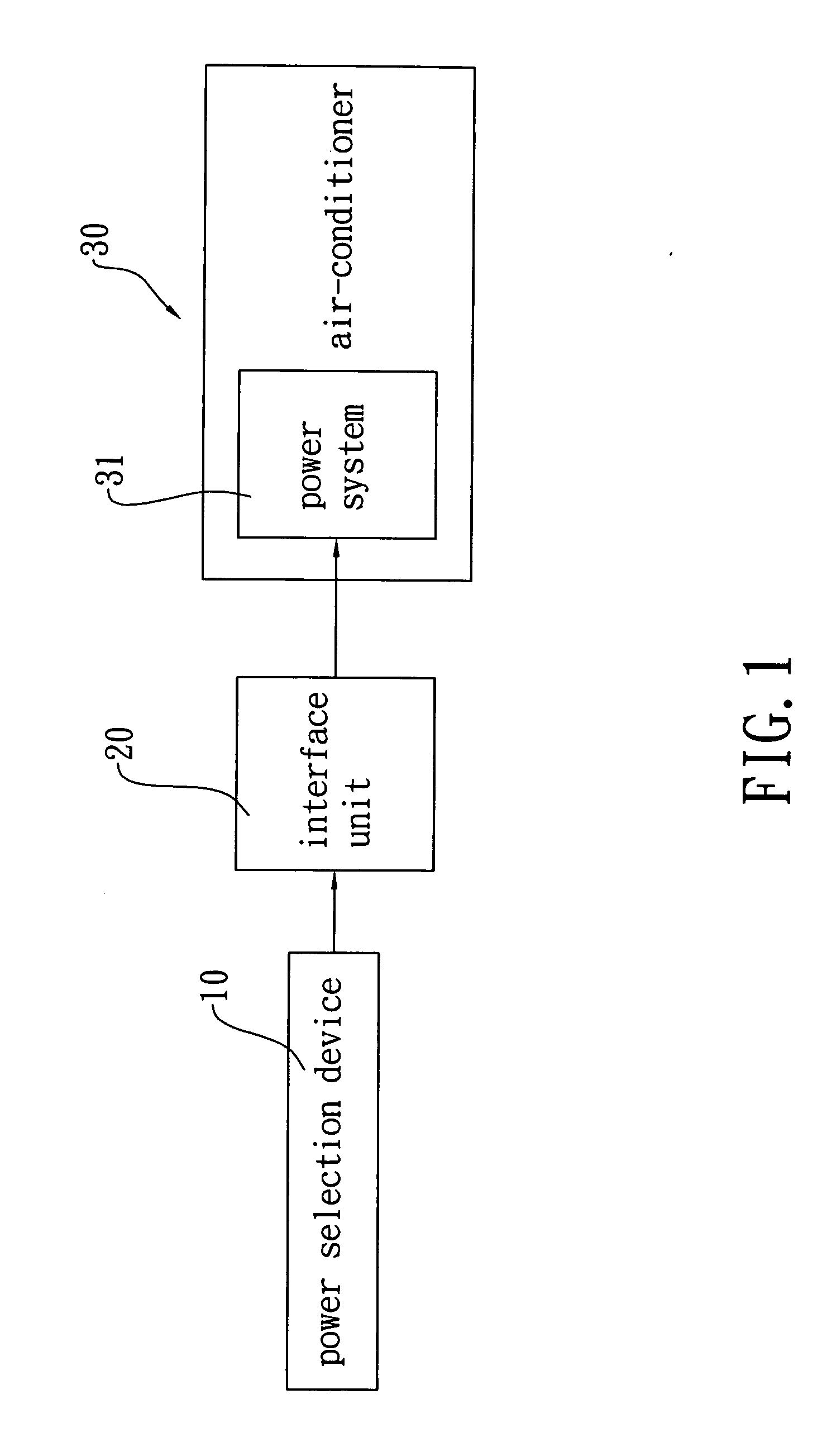
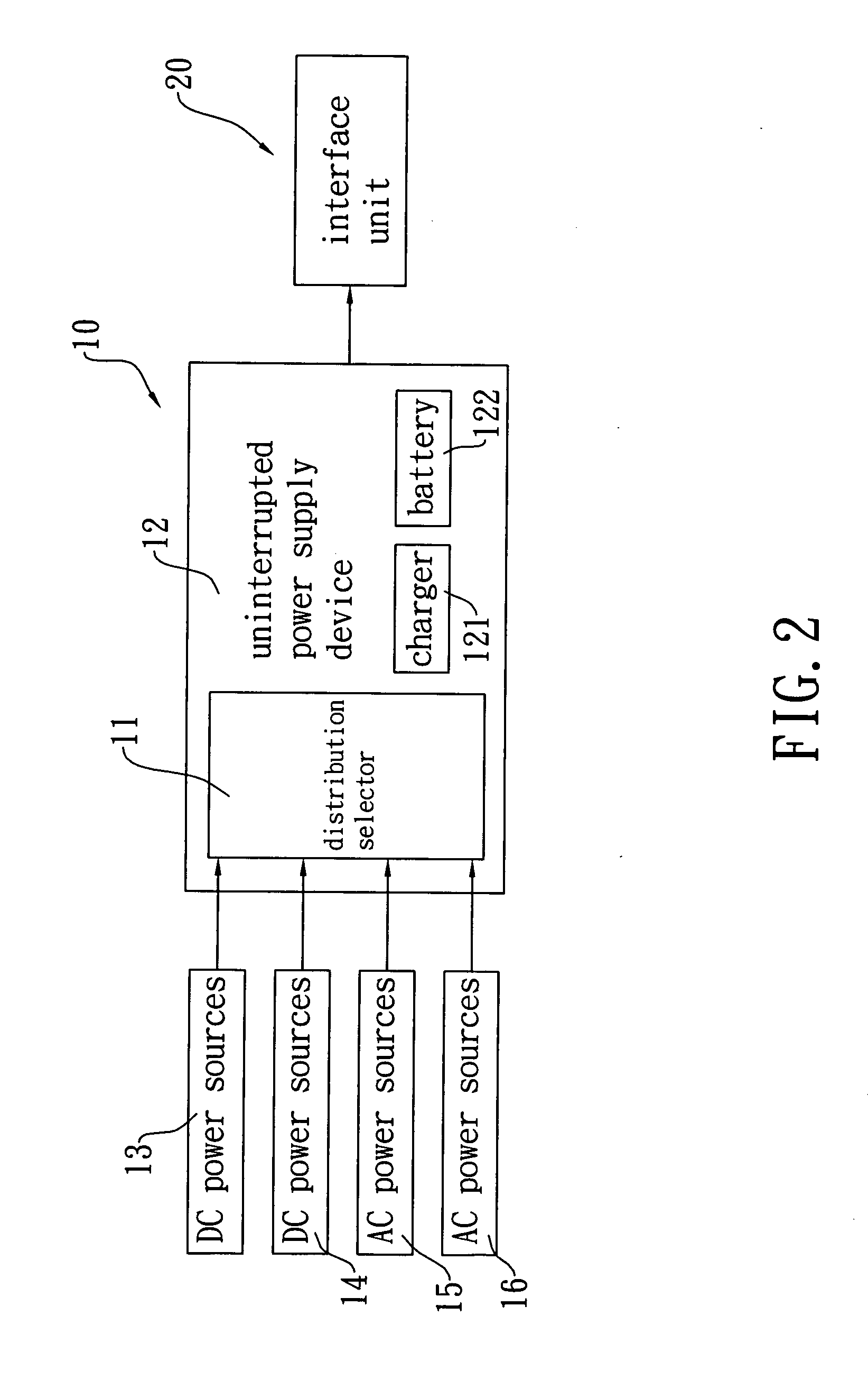
[0005]An objective of the present invention is to provide a power selection system for an air conditioner, which features a combination of a power selection device, an interface unit, and an air conditioner, wherein the power selection device comprises a selection distributor that controls selection of power inputs, which can be either direct-current (DC) power sources or alternate-current (AC) power sources so that power supplied to the air conditioner is from a different power source or a combination of multiple power sources selected from various power sources in different periods of time in accordance with preset arrangement done by a user to there enhance the practicability of the present invention.
[0006]Another objective of the present invention is to provide a power selection system for an air conditioner, which features a combination of a power selection device, an interface unit, and an air conditioner, wherein the interface unit comprises electrical receptacles formed in accordance with power systems of various air conditioners so that the power selection system of the present invention is fit for air conditioners of various brands available in the market to thereby enhance the convenience of the present invention.

Problems solved by technology

Apparently, the electric main is no longer an idea power source to suit the need of the future market.
Apparently, an additional processing that converts the AC power into the DC power is required for the inverter air conditioner and due to the fact that the conversion from the AC power to the DC power is a low efficiency process, using the electrical main to power the inverter air conditioner is economically less efficient.

Method used


Image

  • Power selection system for air conditioner
  • Power selection system for air conditioner
  • Power selection system for air conditioner

Examples


Embodiment Construction

[0012]With reference to the drawings and in particular to FIGS. 1-3, the present invention provides a power selection system specifically for an air conditioner. The power selection device comprises a power selection device, generally designated at 10, which comprises a distribution selector 11 and an uninterrupted power supply device 12. The distribution selector 11 is arranged inside the uninterrupted power supply device 12 and functions to select power input among direct-current (DC) power sources 13, 14 and alternate-current (AC) power sources 15, 16, which can be at least one of a plurality of power sources including for example solar power generation, wind power generation, hydraulic power generation, and an electric main, for proper distribution of the input power supply among these power sources to realize diversification of supply of power. The distribution selector 11 is comprised of a plurality of capacitors, an inductor, a power factor correction / PV (photovoltaic) invert...


PUM


Abstract

A power selection system is provided for an air conditioning system, including a power selection device, an interface unit, and an air conditioner. The power selection device includes a distribution selector and an uninterrupted power supply device. The distribution selector is arranged inside the uninterrupted power supply device. The distribution selector controls selection of power input of the power selection device among multiple power sources. The interface unit is connected to the power selection device. The air conditioner includes a power system, which is connected to the interface unit. As such, the system, as a whole, can be arranged in accordance with the user's need to receive a power input or a combination of multiple power inputs selected from multiple power sources in different periods of time and is fit for air conditioners of different brands available in the market.

Description

FIELD OF THE INVENTION[0001]The present invention relates to a power selection system for an air conditioner, and in particular to a system comprising a combination of a power selection device, an interface unit and an air conditioner, wherein the power selection device comprises a distribution selector for receiving and selecting among multiple power sources, including both alternate-current (AC) power sources and direct-current (DC) power source, to supply a selectively, combined power to the air conditioner to thereby feature multiple selections of power input, so as to be applicable to private and public places, such as home, office, and markets, to serve as air conditioning facility thereof.BACKGROUND OF THE INVENTION[0002]Conventionally, an air conditioner is powered by electrical main. However, with the change of the philosophy of power consumption, various substitute and sustainable power sources are now being proposed, including hydraulic power generation, wind power genera...

Claims


Application Information

Patent Timeline
IPC IPC(8): F25B27/00
CPCH02J9/06F24F11/0086F24F11/30F24F11/52F24F11/88
Inventor YEH, MING-HSIANG
Owner YEH MING HSIANG
Learn More