Color sensor unit for use in display device, color measuring device for use in display device, display system incorporated with color sensor unit, and display calibration method

a color sensor and display device technology, applied in the field of color sensors, can solve the problems of sharp increase in chromaticity error, increase in production cost, and inability to have optical systems in the calibration system of the crt calibrator, and achieve the effect of accurately measuring the luminance value and chromaticity value of the display devi

Inactive Publication Date: 2009-07-16
KONICA MINOLTA SENSING INC
View PDF2 Cites 26 Cited by
  • Summary
  • Abstract
  • Description
  • Claims
  • Application Information

AI Technical Summary

Benefits of technology

[0012]In view of the above, it is an object of the present invention to provide a color sensor unit, for use in a display device, which enables to accurately measure a luminance value and a chromaticity value of the display device, even with use of a sensor having a wide light receiving angle, as well as a color measuring device for use in a display device, a display system incorporated with the color sensor unit, and a display calibration method.

Problems solved by technology

In addition, the CRT calibrator does not have an optical system such as a lens for reducing a light receiving angle in order to suppress an increase in production cost.
Also, as is obvious from FIG. 8, a chromaticity error is sharply increased, as the luminance becomes smaller than 40 cd / m2.
In this condition, in the case where the luminance and the chromaticity of the liquid crystal display device are measured by the aforementioned color sensor having a wide light receiving angle, a large error in a measurement result may be generated depending on the gradation.
Accordingly, in the technology disclosed in D1, it may be difficult to accurately correct a luminance / chromaticity error, even if a correction coefficient is multiplied to a measurement value.

Method used


Image

  • Color sensor unit for use in display device, color measuring device for use in display device, display system incorporated with color sensor unit, and display calibration method
  • Color sensor unit for use in display device, color measuring device for use in display device, display system incorporated with color sensor unit, and display calibration method
  • Color sensor unit for use in display device, color measuring device for use in display device, display system incorporated with color sensor unit, and display calibration method

Examples


Embodiment Construction

[0024]In the following, an embodiment of the invention is described referring to the drawings. Elements having the same reference numerals throughout the drawings indicate identical elements, and repeated description thereof is omitted, as necessary.

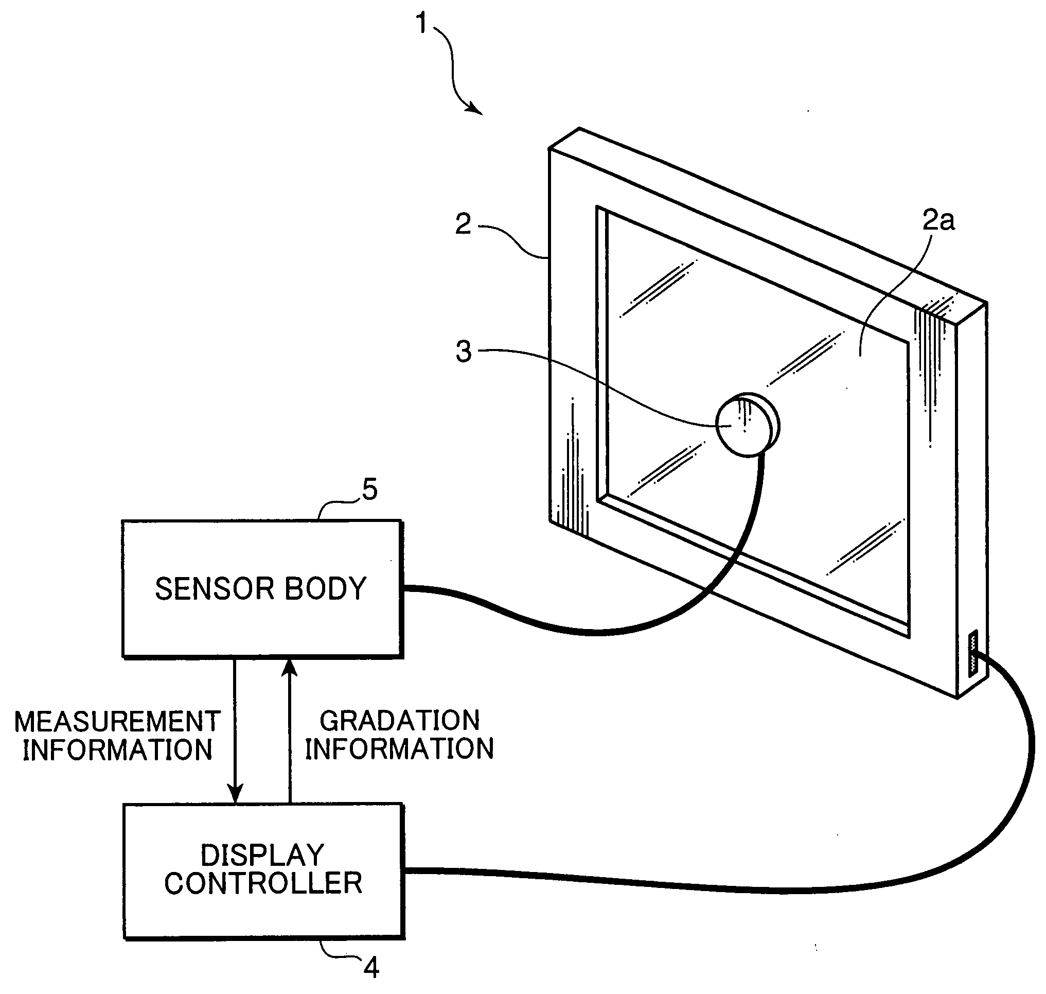
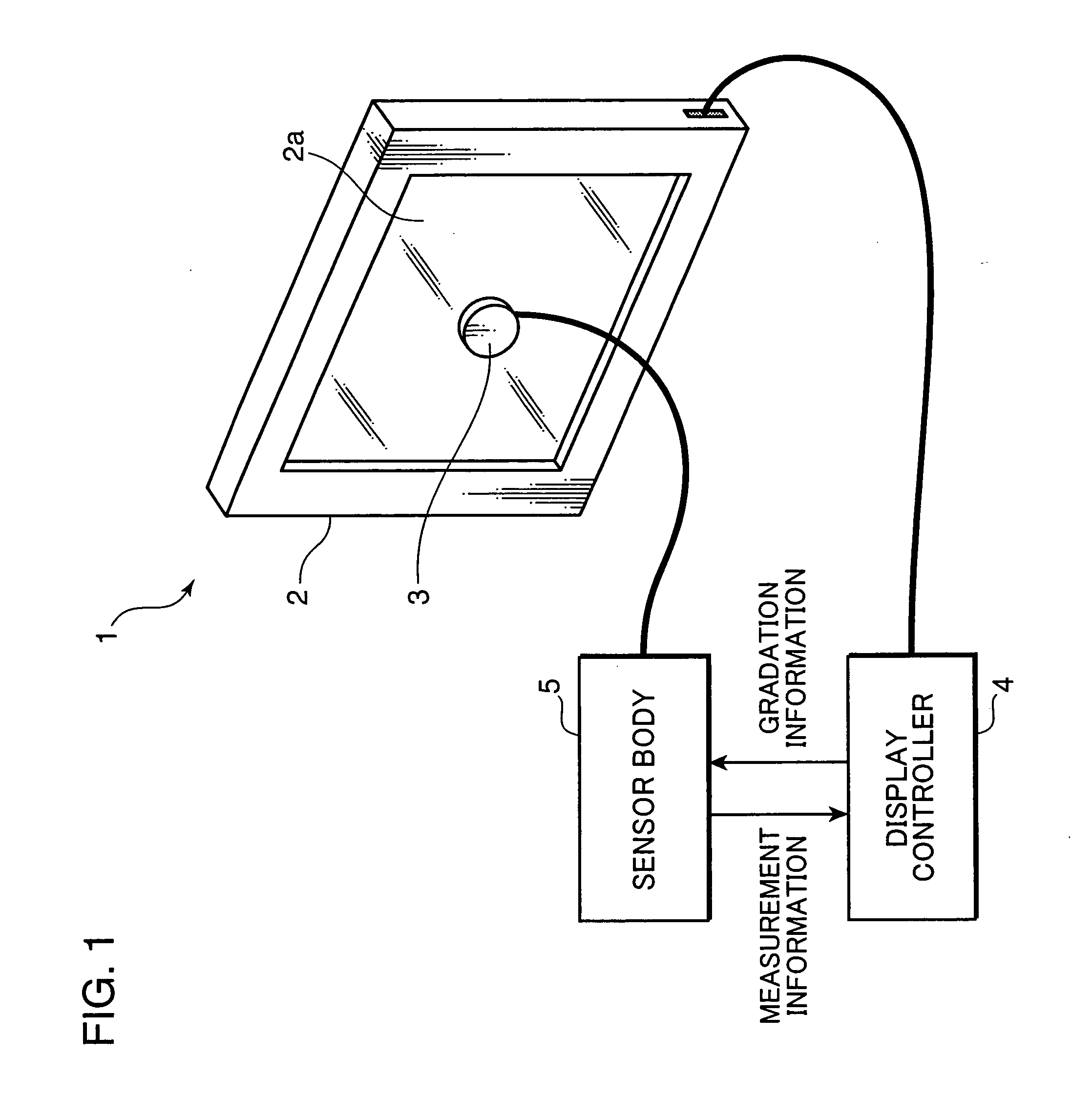
[0025]FIG. 1 is a perspective view showing an external appearance of a liquid crystal display system 1, as an example of a display system embodying the invention. As shown in FIG. 1, the liquid crystal display system 1 includes a high-quality liquid crystal display device 2 whose luminance and chromaticity are required to be calibrated, a display controller 4, a sensor unit 3, and a sensor body 5. The sensor unit 3 and the sensor body 5 constitute an example of a color sensor unit for use in a display device. The sensor body 5 is constituted of e.g. a personal computer. The display controller 4 is constituted of e.g. an image signal processing circuit and a computation processing circuit. Each of USB connectors or a like device is connec...


PUM


Abstract

In a color sensor unit for use in a display device, a color measuring device for use in a display device, a display system and a display calibration method of the invention, a CPU is operable to calculate a luminance value or a chromaticity value substantially equivalent to that to be obtained by a measuring device having a light receiving angle smaller than a light receiving angle of a sensor, by correcting a luminance value or a chromaticity value measured by the sensor based on gradation information from the display device.

Description

[0001]This application is based on Japanese Patent Application No. 2008-3560 filed on Jan. 10, 2008, the contents of which are hereby incorporated by reference.BACKGROUND OF THE INVENTION AND RELATED ART STATEMENT[0002]1. Field of the Invention[0003]The present invention relates to a color sensor for measuring a luminance and a chromaticity of an LCD (liquid crystal display) device in calibrating the luminance and the chromaticity of the liquid crystal display device, a display system incorporated with the color sensor, and a display calibration method.[0004]2. Description of the Related Art[0005]It is necessary to calibrate luminance and chromaticity variations of a high-quality monitor to be used in e.g. a printing field or a medical field. In calibrating luminance and chromaticity variations of a CRT monitor, conventionally, a compact color sensor e.g. a CRT calibrator produced by Konica Minolta may be used. The CRT calibrator is constructed in such a manner that: light from a CR...

Claims


Application Information

Patent Timeline
Patent Type & Authority Applications(United States)
IPC IPC(8): G09G5/00
CPCG09G3/2092G09G3/3611G09G2360/145G09G2320/0693G09G2320/0242
Inventor HIBI, KENICHIRO
Owner KONICA MINOLTA SENSING INC
Why Eureka
Try Eureka