Electronic apparatus and method of controlling electronic apparatus

a technology of electronic equipment and electronic components, applied in the direction of digital output to print units, instruments, digitally marking record carriers, etc., can solve the problems of text information and text information being difficult to view

Inactive Publication Date: 2009-07-16
SONY CORP
View PDF9 Cites 0 Cited by
  • Summary
  • Abstract
  • Description
  • Claims
  • Application Information

AI Technical Summary

Benefits of technology

[0008]An operation screen for allowing a user to operate an electronic apparatus such as a printing apparatus or digital still camera as described above using a GUI (Graphic User Interface) is normally adapted to the resolution of a display section incorporated in the electronic apparatus. Therefore, when such a screen is displayed using high-vision images on a digital television receiver, a problem arises in that text information is hard to view because characters of the text will appear in a very bold form. On the contrary, in the case that the operation screen is adapted to the resolution of high-vision mages, when the operation screen is displayed on a display section incorporated in the electronic apparatus such as a printing apparatus or digital still camera, a problem arises in that the text information is hard to view because the characters of the text are displayed with blurs.

Problems solved by technology

Therefore, when such a screen is displayed using high-vision images on a digital television receiver, a problem arises in that text information is hard to view because characters of the text will appear in a very bold form.
On the contrary, in the case that the operation screen is adapted to the resolution of high-vision mages, when the operation screen is displayed on a display section incorporated in the electronic apparatus such as a printing apparatus or digital still camera, a problem arises in that the text information is hard to view because the characters of the text are displayed with blurs.

Method used


Image

  • Electronic apparatus and method of controlling electronic apparatus
  • Electronic apparatus and method of controlling electronic apparatus
  • Electronic apparatus and method of controlling electronic apparatus

Examples


Embodiment Construction

[0026]Embodiments of the invention will now be described in detail with reference to the drawings.

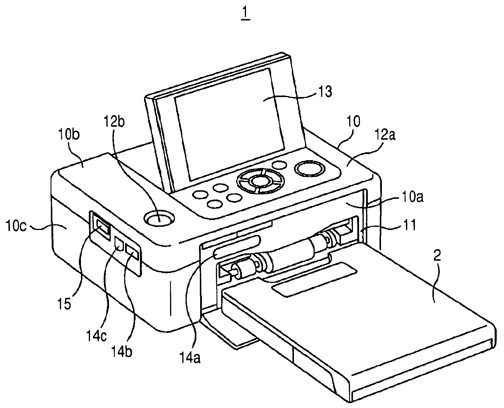
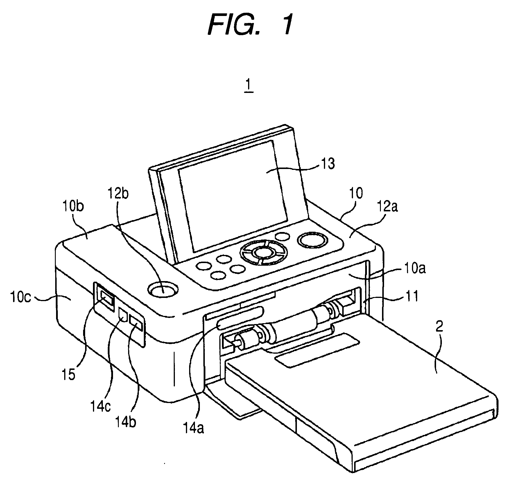
[0027]The invention may be applied to a printing apparatus which has display means for displaying an image for display associated with image data to be printed. An embodiment of the invention will be described below by taking a printing apparatus 1 as shown in FIG. 1 as an example of such a printing apparatus.

[0028]The printing apparatus 1 has an opening 11 formed on a front surface 10a of an apparatus body 10 to allow a paper tray 2 containing sheets of paper to be mounted, and sheets of paper are inserted and discharged to and from the apparatus body 10 at the side of the apparatus where the front surface 10a is located. Operation buttons 12a and 12b and a monitor 13 for displaying an image to be printed are provided on a top surface 10b of the printing apparatus 1. The printing apparatus 1 includes a recording media slot 14a, serving as an external interface, provided on the front su...


PUM


Abstract

An electronic apparatus has a display section displaying an image in a predetermined resolution. The apparatus includes a fetching section fetching image data, a processing section processing the form of characters of character data to be added to the image data fetched by the fetching section, a synthesis section synthesizing the image data fetched by the fetching section and the character data whose character form has been processed, an output section outputting the image data out of the apparatus to display the image in a resolution different from the predetermined resolution, and an output control section for outputting the image data synthesized by the synthesis section to the display section and output section. The processing section processes the form of characters of the character data according to the resolution of the image to be displayed at the destination to which the data are output by the output control section.

Description

CROSS REFERENCES TO RELATED APPLICATIONS[0001]The present invention contains subject matter related to Japanese Patent Application JP 2008-006015 filed in the Japanese Patent Office on Jan. 15, 2008, the entire contents of which being incorporated herein by reference.BACKGROUND OF THE INVENTION[0002]1. Field of the Invention[0003]The present invention relates to an electronic apparatus having display means for displaying an image in a predetermined resolution and a method of controlling the electronic apparatus.[0004]2. Description of the Related Art[0005]In order to allow a user to select an image to be printed, a printing apparatus for printing image data according to the related art displays images to be printed in a QVGA size using, for example, a built-in monitor, and an output terminal may be provided for outputting the images to be printed to an external display apparatus to display the images (see JP-A-2007-274225 (Patent Document 1)).[0006]A digital still camera not only di...

Claims


Application Information

Patent Timeline
Patent Type & Authority Applications(United States)
IPC IPC(8): H04N1/60
CPCH04N1/00129H04N1/00167H04N1/00278H04N1/00347H04N1/00458H04N1/2158H04N2201/3273H04N1/387H04N1/40068H04N2201/0082H04N2201/0089H04N2201/3266H04N1/32325
Inventor MAENO, TOMOHARUKURASAWA, TOMOKISUZUKI, SHOHEI
Owner SONY CORP
Why Eureka
Try Eureka