Lighting apparatus for motorcycle

a technology for motorcycles and light fittings, which is applied in the direction of lighting and heating equipment, cycle equipment, light support devices, etc., can solve the problems of reducing the visibility of the motorcycle to a third party, affecting the safety of the motorcycle, and being susceptible to vibration, so as to achieve reliable security of the lighting body

Inactive Publication Date: 2012-08-28
HONDA MOTOR CO LTD
View PDF27 Cites 0 Cited by
  • Summary
  • Abstract
  • Description
  • Claims
  • Application Information

AI Technical Summary

Benefits of technology

[0007]In accordance with the first aspect of the present invention, surfaces of the housing and the lid in abutment with each other, specifically, a division surface between the two elements is disposed on the center side of the vehicle body, specifically, a spot that is hard to view from an outside. This makes for good appearance. In addition, the lighting body can be installed only by way of a side of the housing through the side opening. This ensures good workability.
[0009]In accordance with the second aspect of the present invention, the wire can be wired inside the housing. This improves appearance with no wires exposed on an outer periphery of the housing. Should water enter from an upper portion along the wire, the wire is guided downwardly of the lighting body and then folded back upwardly. There is therefore no chance of the lighting body being splashed with water. Further, the water, should it enter the housing, is discharged through the drain hole.
[0011]In accordance with the third aspect of the present invention, the lighting body can be positioned by being guided along the rails inside the housing. This allows the lighting body to be installed at a predetermined position inside the housing easily.
[0013]In accordance with the fourth aspect of the present invention, the board, the position of which is restricted by the upper and lower rails, is further screwed in position. This structure and arrangement more reliably secures the lighting body to the housing.

Problems solved by technology

However, because motorcycles are typically smaller than passenger cars and trucks, the visibility of the motorcycle to a third party is often reduced, making it likely that the third party will misjudge the distance and speed of the oncoming motorcycle.
However, the lower end of the front fork is close to the axle and is therefore susceptible to vibrations of wheels occurring from road surface irregularities as the motorcycle runs.

Method used


Image

  • Lighting apparatus for motorcycle
  • Lighting apparatus for motorcycle
  • Lighting apparatus for motorcycle

Examples


first embodiment

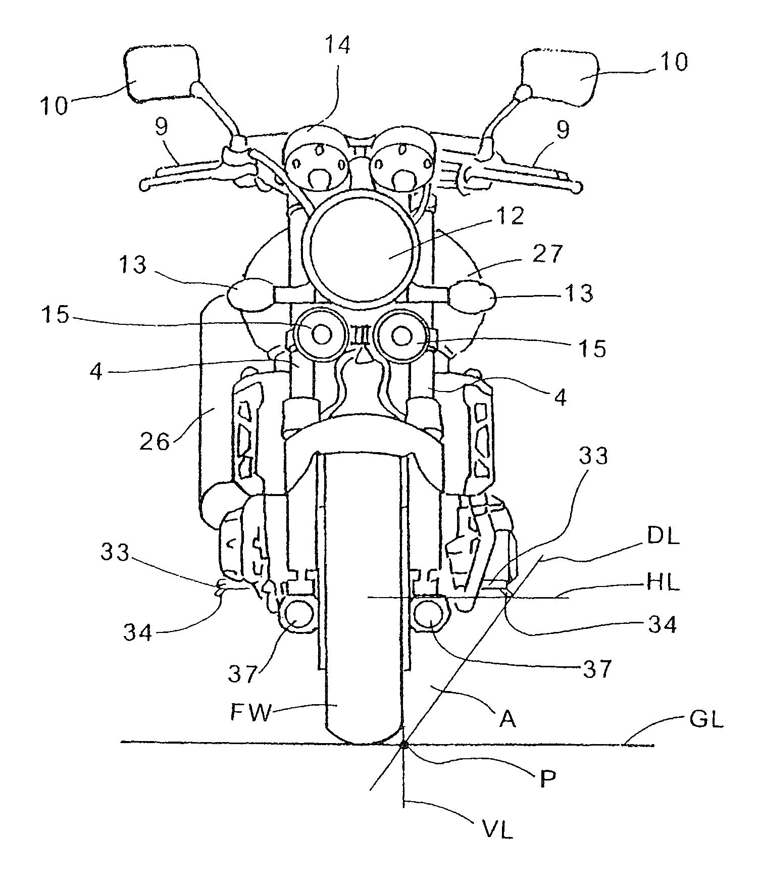
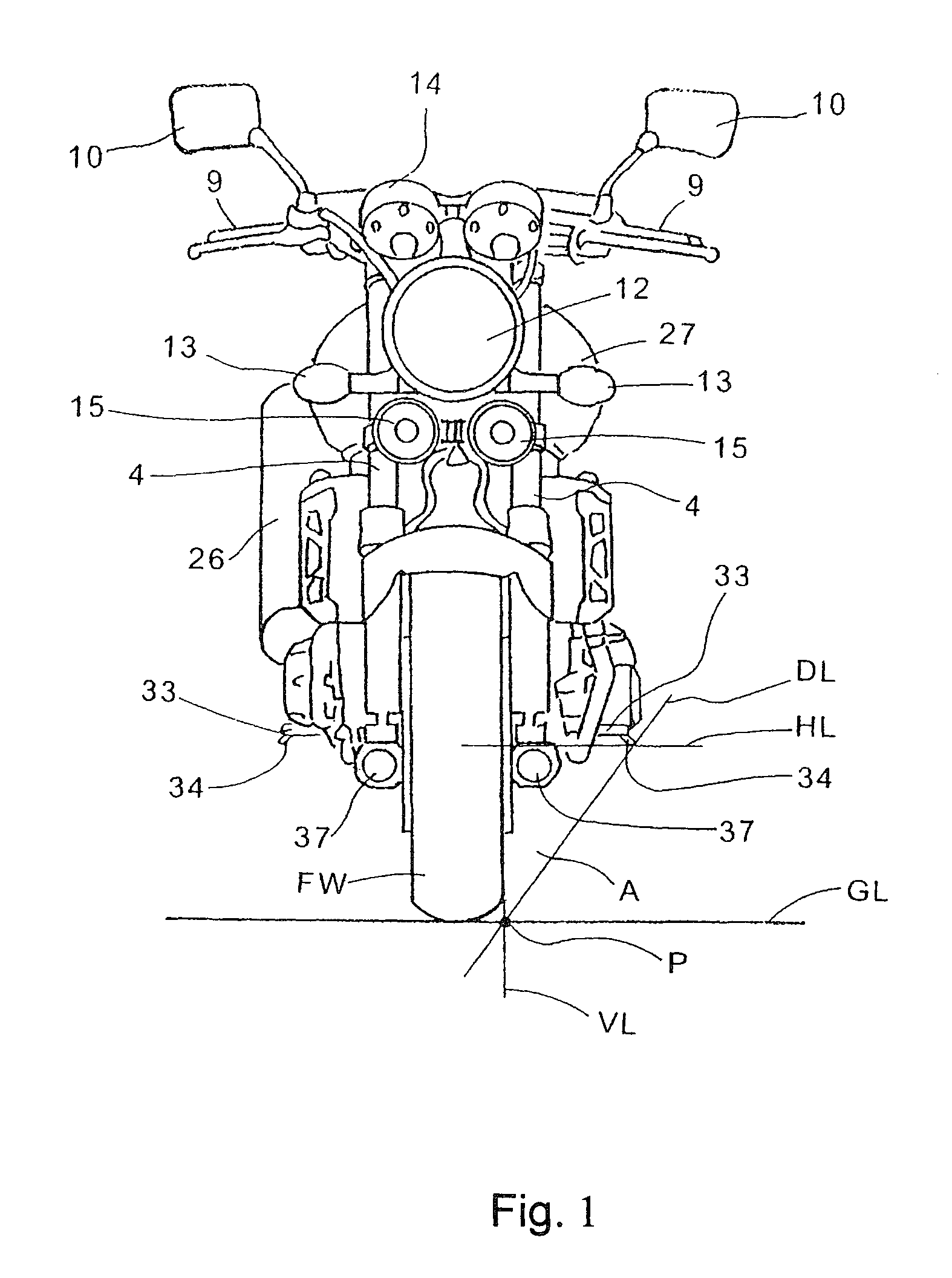
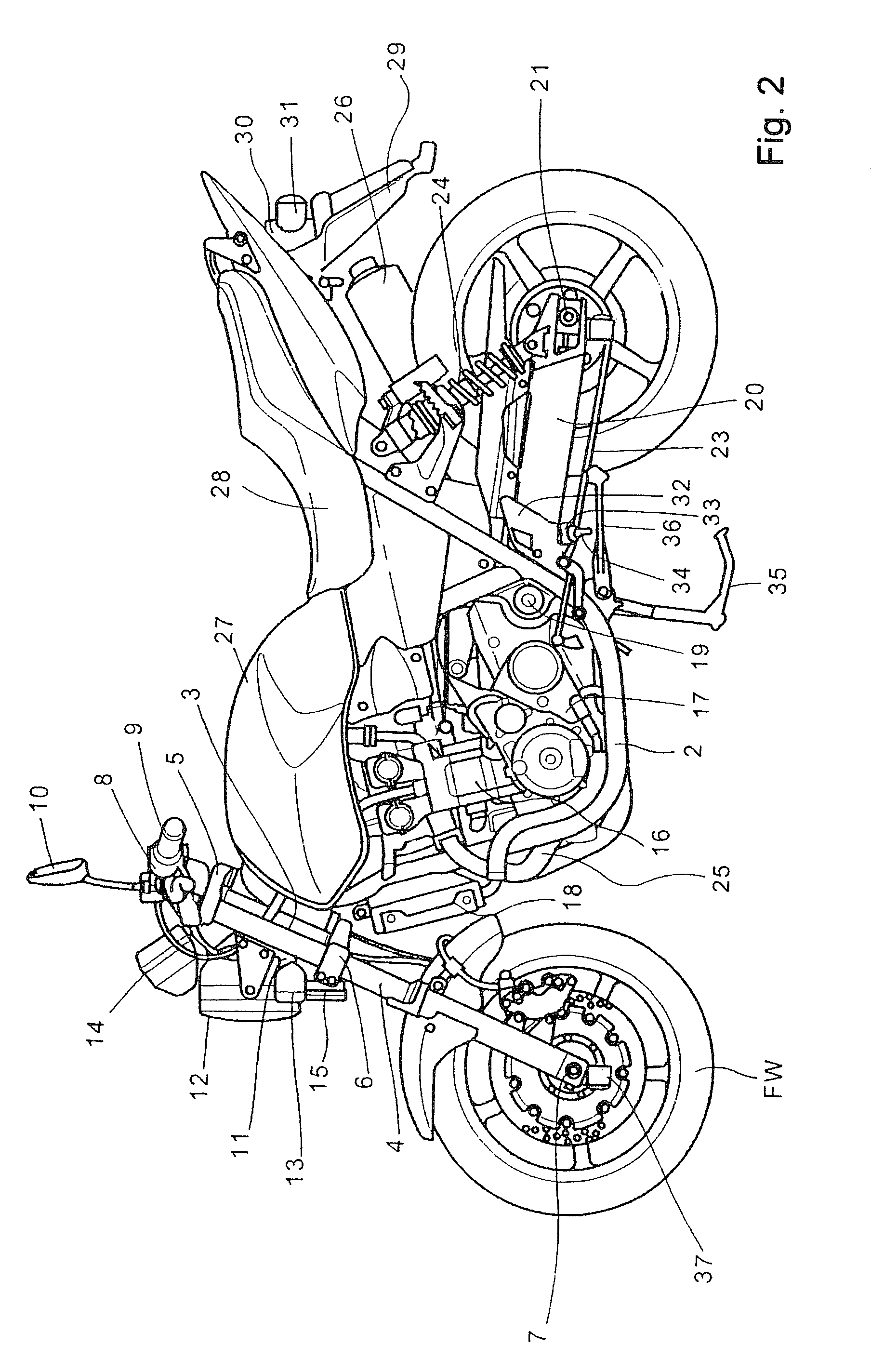
[0027]FIG. 1 is a front view showing a motorcycle according to the present invention. FIG. 2 is a left side elevation view of the motorcycle. A motorcycle 1 includes a frame body 2 composed of a pair of left and right pipe frames. A head pipe 3 joined to a front portion of the frame body 2 rotatably supports a steering stem not shown. The steering stem has upper and lower portions connected to a top bridge 5 and a bottom bridge 6, respectively, of a front fork 4. The front fork 4 is extended downwardly so as to support a front wheel FW via a front wheel axle 7 disposed near a lower end of the front fork 4.

[0028]A handlebar pipe 8 is connected to the top bridge 5. The handlebar pipe 8 is mounted with a grip 9 and a mirror 10. A bracket 11 is joined to the front fork 4. The bracket 11 is mounted with a headlamp 12, a front turn signal lamp 13, and a meter 14. The bottom bridge 6 is attached with a horn 15.

[0029]An engine 16 is mounted on the frame body 2. A transmission 17 is disposed...

second embodiment

[0054]The bottom case 4a may include a slit 60 formed therein, extending from the lower end portion of the bottom case 4a up to a bearing 59 supporting a front wheel axle 7 (see FIG. 2). With the front wheel axle 7 inserted into the bearing 59, a pinch bolt 61 is inserted into a bolt hole 62 and tightened, so that the front wheel axle 7 is secured in the bearing 59. The bracket 57 of the lighting apparatus 37 has a hole 63 formed therein, through which the pinch bolt 61 can be passed. When the lighting apparatus 37 is applied to the bottom case 4a, the hole 63 is aligned with the bolt hole 62 in the bottom case 4a. Accordingly, the pinch bolt 61, which is commonly used for tightening the bearing 59 to thereby fix the axle, can also be used to secure the lighting apparatus 37 to the bottom case 4a. According to the present invention, the bottom case 4a is adapted to be clamped by the bracket 57 and the guide 58. This arrangement allows a single bolt to fix the lighting apparatus 37 t...


PUM


Abstract

A lighting apparatus has a housing and is disposed at a lower end of a front fork of a motorcycle. The housing includes a front opening disposed on a side of a radiation direction of a lighting body and a side opening disposed on a center side in a width direction of a motorcycle. The side opening in the housing, covered by a lid, is wide enough for the lighting body to pass through. The housing includes a wire guide for withdrawing an electric wire and a drain hole formed in a bottom portion of the housing. The lighting body is fixed on a board. The housing includes rails disposed on an upper wall portion and a lower wall portion thereof, into which an upper end and a lower end of the board are to be fitted so as to position the lighting body in a longitudinal direction.

Description

TECHNICAL FIELD[0001]The present invention relates generally to lighting apparatuses for a motorcycle, in particular, a lighting apparatus disposed to improve visibility of a third person.BACKGROUND OF THE INVENTION[0002]Japanese Patent Laid-Open No. 2001-334976 (hereinafter, “JP '976”) discloses a motorcycle with a lamp unit for visibility purpose such that pedestrians and vehicle drivers can more readily recognize the presence of the motorcycle. However, because motorcycles are typically smaller than passenger cars and trucks, the visibility of the motorcycle to a third party is often reduced, making it likely that the third party will misjudge the distance and speed of the oncoming motorcycle.[0003]Japanese Patent Laid-Open No. 2003-300488 (hereinafter, “JP '488) discloses a motorcycle in which at least one of lighting bodies of a lighting body system of a motorcycle is disposed at a level equal to, or lower than, an axle and forward of a rearmost portion of a front wheel or rear...

Claims


Application Information

Patent Timeline
Patent Type & Authority Patents(United States)
IPC IPC(8): F21V33/00F21W107/17
CPCB62J6/02B62J11/00B62J6/026
Inventor HAYAKAWA, KOSHIKATAYAMA, MUTSUMIMORIMOTO, JUN
Owner HONDA MOTOR CO LTD
Why Eureka
Try Eureka