Projecting Head for a Laser Pointer for Presenting Different Projected Patterns

a laser pointer and projector technology, applied in the field of laser pointer projector head, can solve the problem of inconvenient change of projector head by the presenter

Inactive Publication Date: 2009-07-16
CHU HENG PING
View PDF4 Cites 14 Cited by
  • Summary
  • Abstract
  • Description
  • Claims
  • Application Information

AI Technical Summary

Problems solved by technology

However, the presenter has to inconveniently change different projecting heads to show different projected patterns during presentations.

Method used


Image

  • Projecting Head for a Laser Pointer for Presenting Different Projected Patterns
  • Projecting Head for a Laser Pointer for Presenting Different Projected Patterns
  • Projecting Head for a Laser Pointer for Presenting Different Projected Patterns

Examples


Embodiment Construction

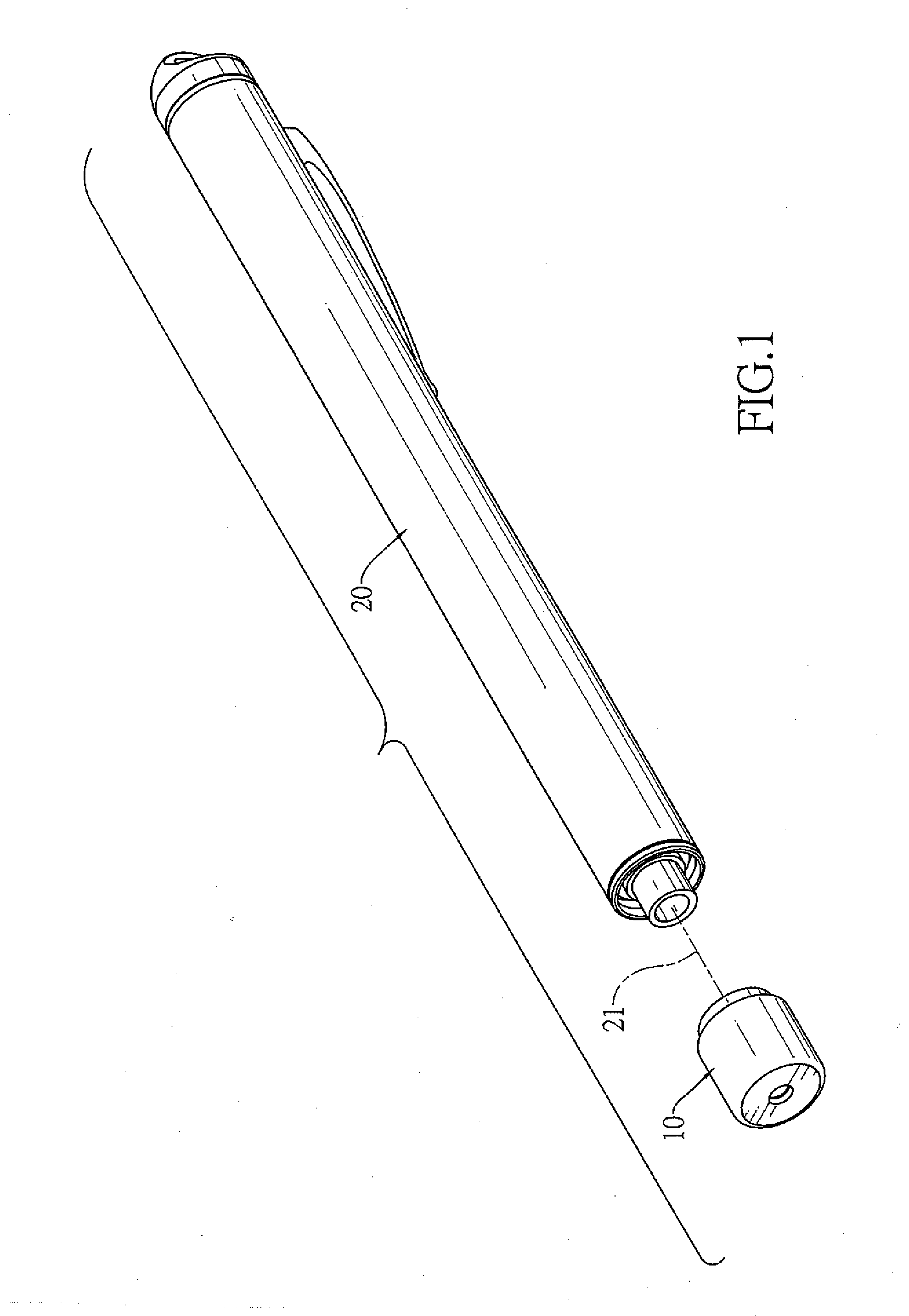
[0017]With reference to FIG. 1, a projecting head (10) for presenting different projected patterns in accordance with the present invention is mounted on a laser pointer (20) that emits a laser light through a laser emitting route.

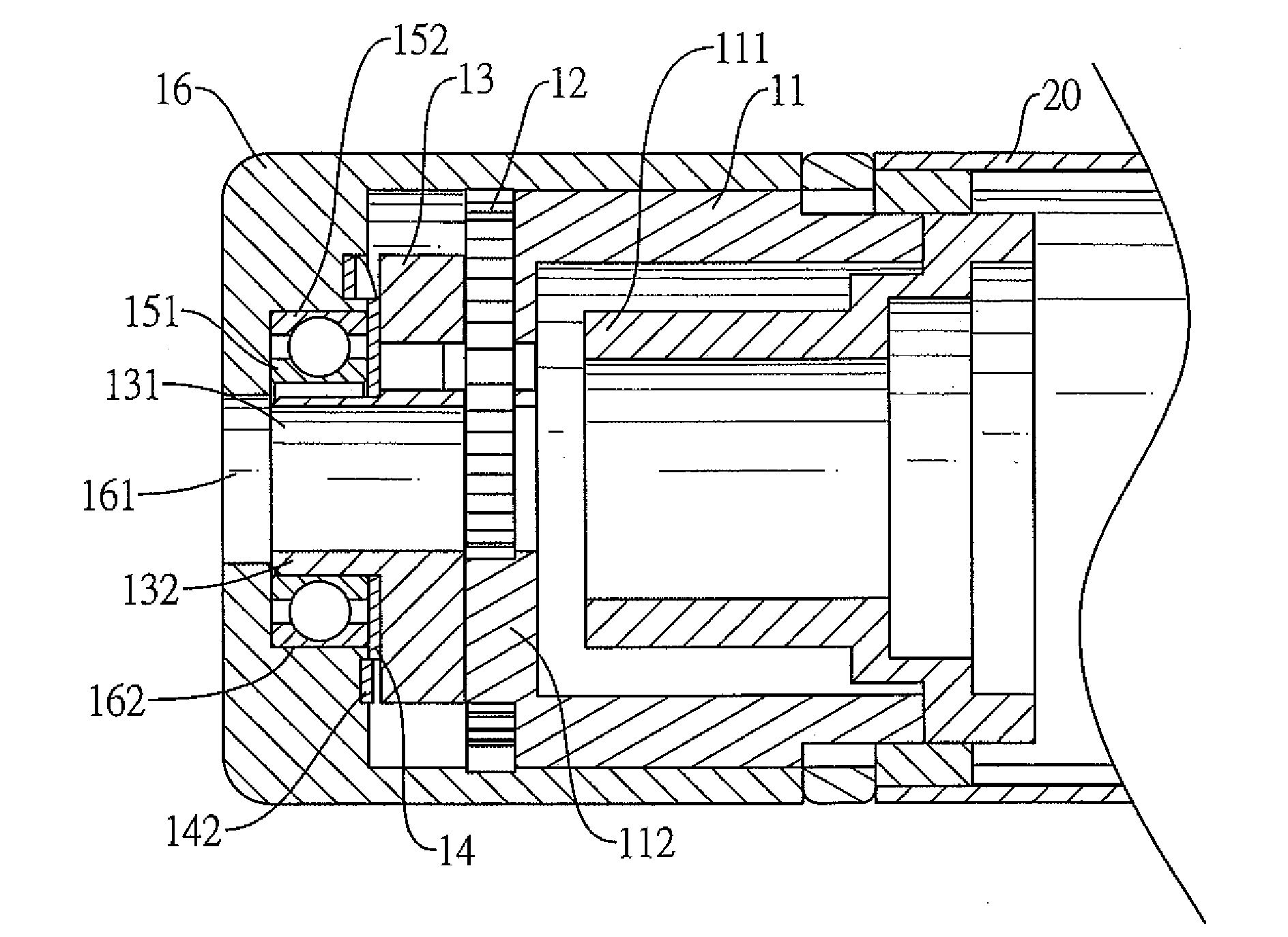
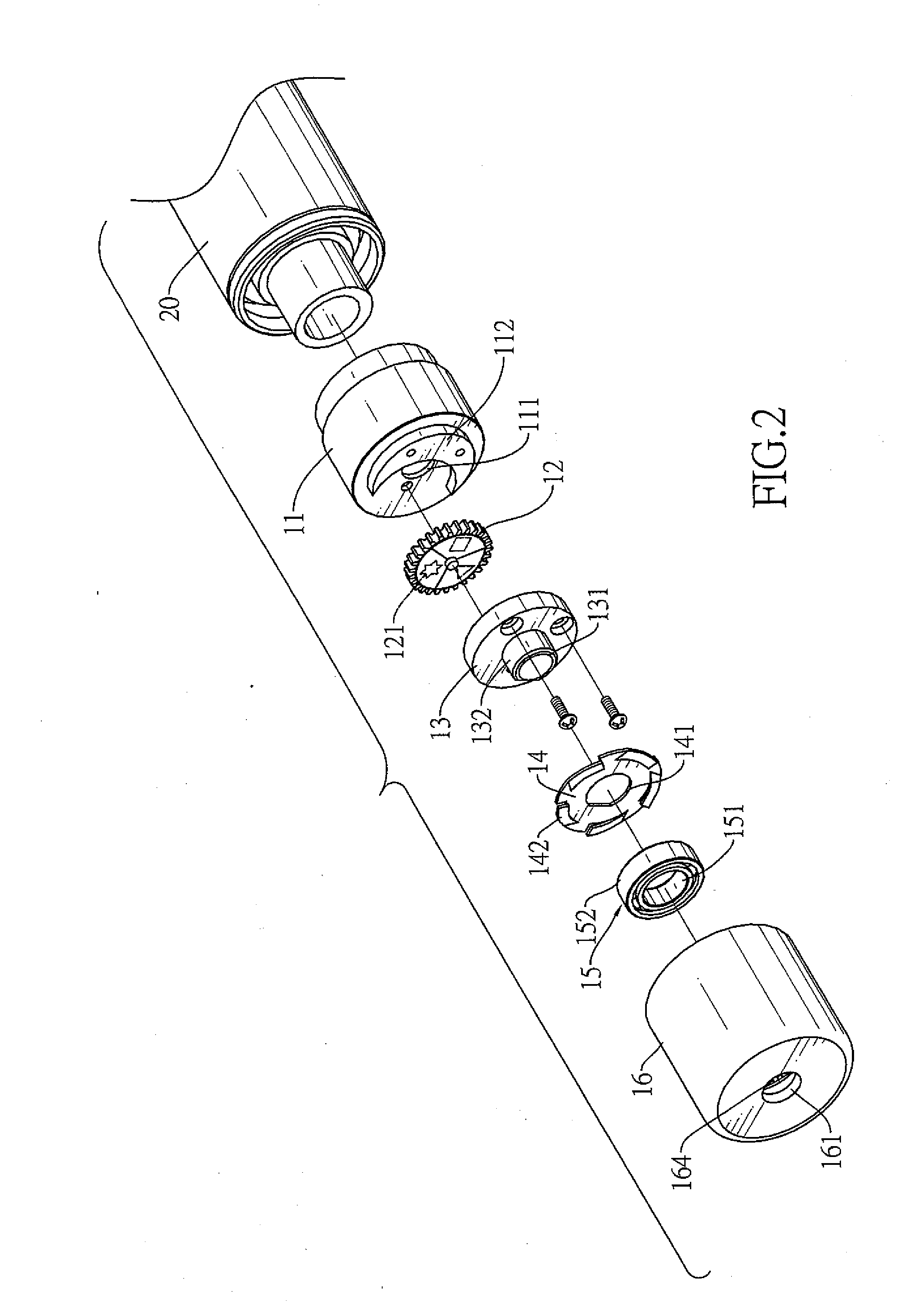
[0018]With further reference to FIGS. 2 and 3, the projecting head (10) comprises a base (11), a gear wheel (12), a positioning stage (13), an optional ratchet (14), an optional bearing (15) and a cap (16).

[0019]The base (11) has a front end, a rear end, a laser channel (111) and an optional protrusion (112). The rear end of the base (11) is mounted on the laser pointer (20). The laser channel (111) is formed through the base (11), corresponds to the laser emitting route of the laser pointer (20) to allow the laser lights to pass through the base (11). The protrusion (112) is formed on the front end of the base (11).

[0020]The gear wheel (12) is mounted rotatably on the front end of the base (11), is adjacent to and covers the front opening of the laser cha...


PUM


Abstract

A projecting head of a laser pointer has a base, a gear wheel, a positioning stage and a cap. The base has a front end and a laser channel. The laser channel is formed through the base to allow a laser light to pass through. The gear wheel is mounted rotatably on the front end of the base and has multiple different imaging patterns. Each imaging pattern selectively covers the front opening of the laser channel of the base when rotating the gear wheel. The positioning stage holds the gear wheel between the base and the positioning stage and has a passage that allows the laser light to pass through. The cap has an annular gear engaging the gear wheel. Therefore, the gear wheel will rotate when the cap is rotated. Consequently, the projecting head will follow the rotating gear wheel to present different projected patterns.

Description

BACKGROUND OF THE INVENTION[0001]1. Field of the Invention[0002]The present invention relates to a projecting head of a laser pointer, and more particularly to a projecting head of a laser pointer for presenting different projected patterns.[0003]2. Description of Related Art[0004]Laser pointers are commonly used during presentations. Presenters can easily point out what to focus on to the listeners because each laser pointers emits laser lights and presents a projected pattern on a presenting screen.[0005]A conventional laser pointer has a stick shaped housing, a laser module and a collimater. An end of the housing has a through hole. The laser module is mounted in the housing and generates and emits light. The collimator is mounted in the housing and collimates the light emitted from the laser module. The collimated light is then projected from the through hole of the housing and presents a dot image on the presenting screen.[0006]Another conventional laser pointer further has mul...

Claims


Application Information

Patent Timeline
Patent Type & Authority Applications(United States)
IPC IPC(8): G02B27/20
CPCG02B27/20
Inventor CHU, HENG-PING
Owner CHU HENG PING
Why Eureka
Try Eureka