

Method, apparatus, and program for measuring sizes of tumor regions
a tumor region and tumor size technology, applied in the field of methods, apparatuses, and programs for measuring tumor regions, can solve the problems of inaccurate evaluation and inability to perform accurate evaluations, and achieve the effect of accurately reflecting the three-dimensional size of tumors
- Summary
- Abstract
- Description
- Claims
- Application Information
AI Technical Summary
Benefits of technology
Problems solved by technology
Method used
Image

Examples
first embodiment
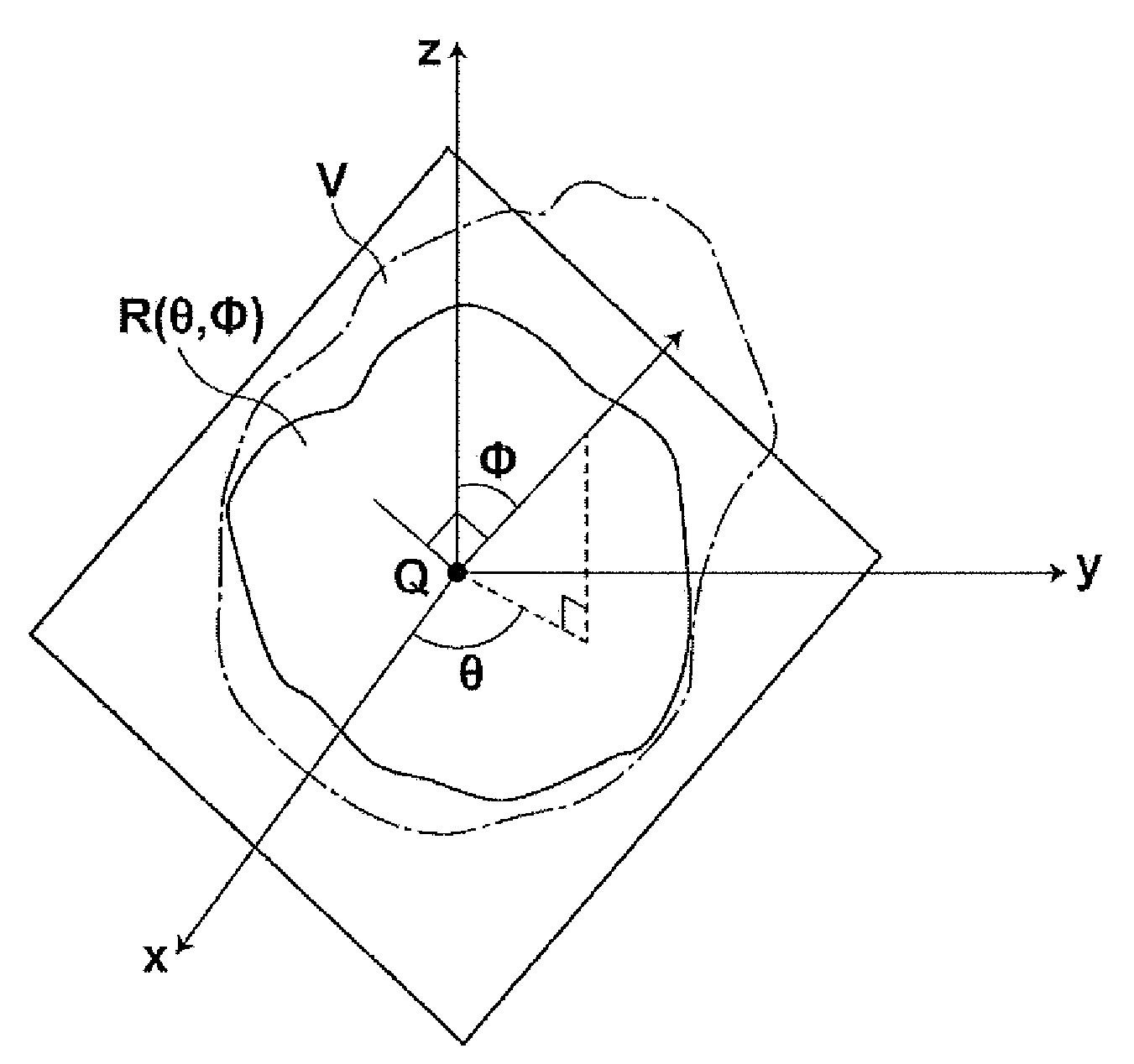
[0076]the process for designating a long axis and a short axis will be described with reference to FIGS. 3 through 5. First, an arbitrary point Q is set within a tumor region V. For example, it can be assumed that each point within the tumor region V has a uniform mass, and the arbitrary point Q may be set at the center of gravity of the tumor region V. Alternatively, the arbitrary point Q may be a position within the input image specified by operator input using a keyboard or a pointing device of the tumor region size measuring apparatus 1.
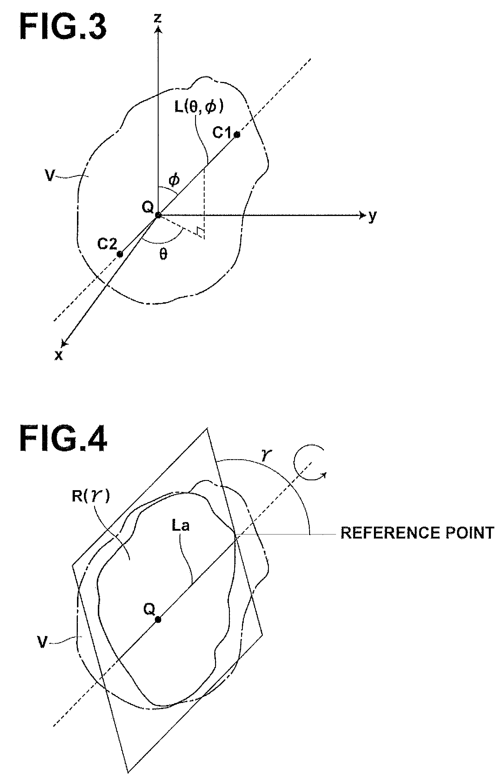
[0077]Next, a line segment having the greatest length from among a plurality of line segments that pass through the set arbitrary point Q and the ends of which are positioned on the outline of the tumor region V, is designated as the long axis. Specifically, a three dimensional coordinate system is set having the arbitrary point Q as its origin, as illustrated in FIG. 3, and directions (θ, φ) (0°≦θ≦360°, 0°≦φ≦180°) emanating from the point Q are ...
second embodiment
[0083]Hereinafter, the process for designating a long axis and a short axis will be described.
[0084]First, an arbitrary point Q is set within a tumor region V which has been determined by the tumor region determining section 10 in the same manner as in the first embodiment.
[0085]Next, a cross section of the tumor region V having the greatest area from among cross sections of the tumor region V that pass through the set arbitrary point Q is detected. Specifically, a three dimensional coordinate system is set having the arbitrary point Q as its origin, as illustrated in FIG. 6, and directions (θ, φ) (0°≦θ≦360°, 0°≦φ≦180°) emanating from the point Q are set. Here, θ represents angles in a direction parallel to the X axis, and φ represents angles in a direction perpendicular to the Z axis. The directions (θ, φ) are varied, by maintaining θ at 0° and sequentially changing φ from 0°, 15°, 30° . . . to 180°; maintaining θ at 15° and sequentially changing φ from (0°), 15°, 30° . . . 165°, (...
third embodiment
[0089]Hereinafter, the process for designating a long axis and a short axis will be described.
[0090]First, a line segment that connects two points on the outline of a tumor region V having the greatest distance therebetween is designated as a long axis La. Specifically, different combinations of two points are selected sequentially, from among a plurality of points P1 (x1, y1); P2 (x2, y2); . . . Pi (xi, yi), which are set on the outline of the tumor region V, as illustrated in FIG. 7. The distances between the combinations of the two points are obtained, and the line segment having the combination of points having the greatest distance therebetween as its ends is designated as the long axis La.
[0091]Next, a cross section Ra3 of the tumor region V having the greatest area from among cross sections of the tumor region V that include the long axis La is detected in the same manner as in the first embodiment. Then, a line segment having the greatest length from among a plurality of lin...
PUM
 Abstract
Description
Claims
Application Information