Vacuum shroud for use with drilling tools

a vacuum shroud and drilling tool technology, applied in the field of vacuum shrouds, can solve the problems of creating undesirable dust and debris, affecting the health of operators, and affecting the health of workers, and can be quite harmful to the health of workers

Inactive Publication Date: 2009-07-16
DUSTLESS DEPOT
View PDF64 Cites 61 Cited by
  • Summary
  • Abstract
  • Description
  • Claims
  • Application Information

AI Technical Summary

Benefits of technology

[0006]In some embodiments described below, a vacuum shroud may be made using a flexible material, enabling it to bend and be used on a non-planar surface. Using a flexible material may allow the shroud to seal better to both flat and curved surfaces, such that the vacuum helps hold the shroud to the workplace more securely.

Problems solved by technology

Drilling and other similar processes create undesirable dust and debris.
The debris often tends to spread in all directions, is usually difficult to remove, and can be harmful to the operator's health.
Many types of debris, such as from fiberglass, can be quite harmful to the health of the worker.
In addition, the dust and debris often collects in the power tool itself, such as in the gears, chuck, or motor, and can cause increased wear and a decrease in the tool's life.
Available devices, however, perform poorly when used for drilling into other substances, such as metal where long strings of metal are generated rather than a fine dust.
These devices are also difficult to use as a person must hold the vacuum hose and shroud in one hand while drilling with the other hand.
While these need not be held independently of the tool, they can inhibit the operator's ability to use the tool, as the bulk of the device and the vacuum hose are cumbersome and limit the ability to accurately position the drill bit.

Method used


Image

  • Vacuum shroud for use with drilling tools
  • Vacuum shroud for use with drilling tools
  • Vacuum shroud for use with drilling tools

Examples


Embodiment Construction

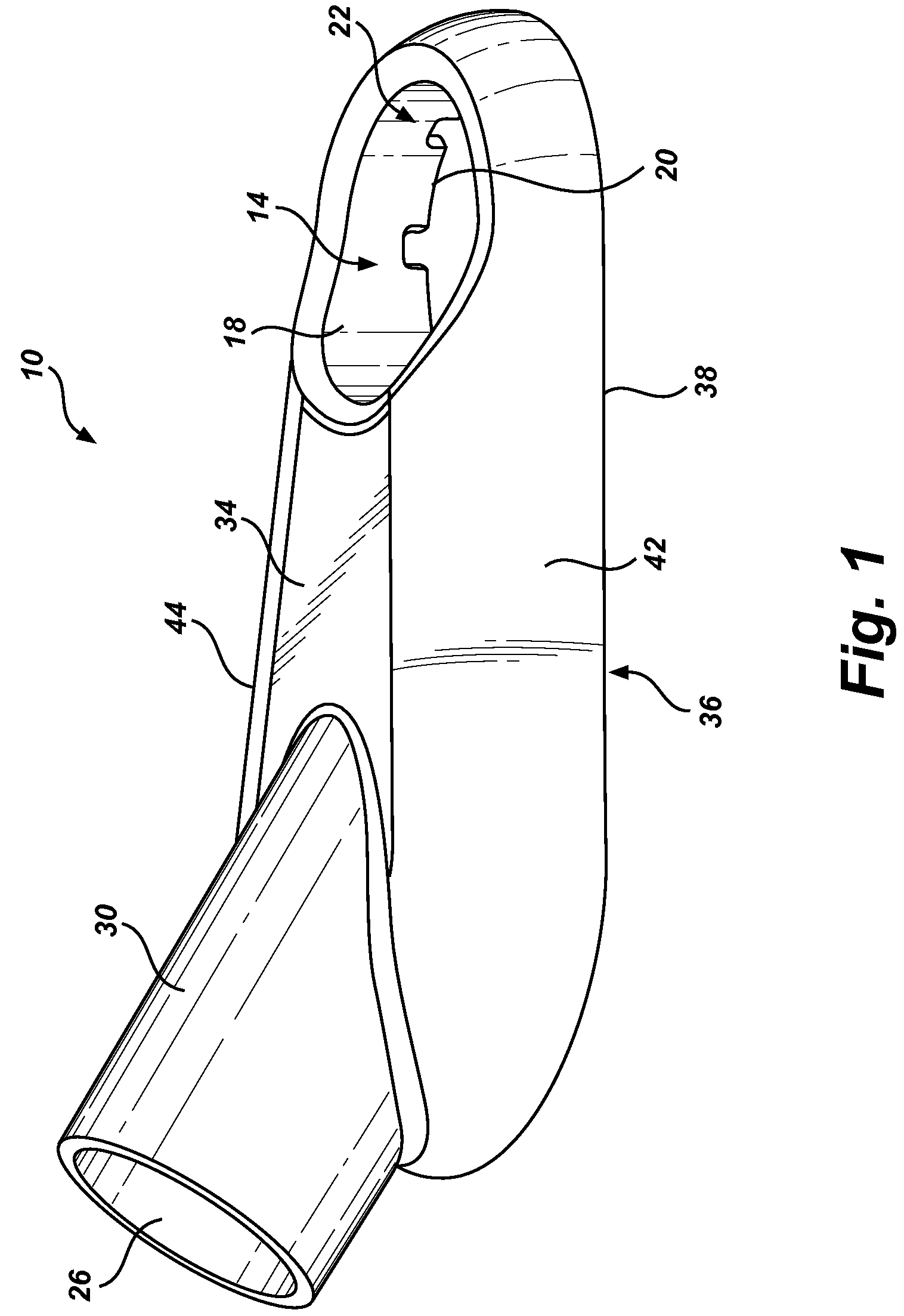
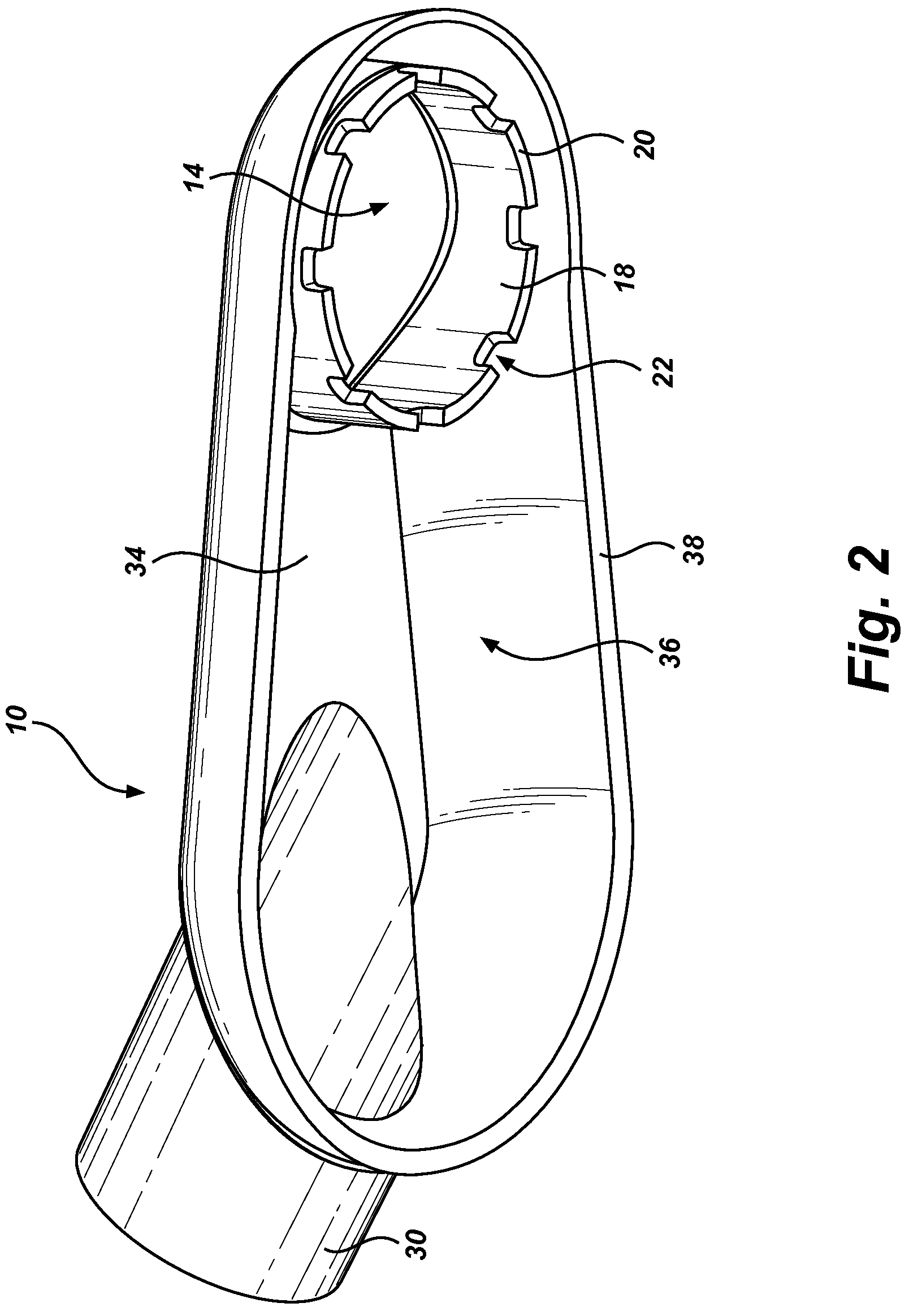
[0017]Turning now to FIG. 1, a top perspective view of an embodiment of a vacuum shroud for drilling tools is shown. Vacuum shroud 10 may include an upper surface 34 connected to lower edge 38, which may be configured to contact a work surface to be drilled, or a surface adjacent thereto. Upper surface 34 and lower edge 38 may be connected by sides 42 and 44, creating enclosed cavity 36 (see FIG. 2) between vacuum shroud 10 and the surface to be drilled.

[0018]Vacuum shroud 10 may include vacuum port 30 connected to upper surface 34 of vacuum shroud 10 with opening 26, which may be connected to a vacuum hose, or which may be formed integrally with a vacuum hose. Vacuum port 30 may also be open to cavity 36. Debris created by the drilling process may be removed by a vacuum (not shown) connected to vacuum port 30 through opening 26 through cavity 36.

[0019]Upper surface 34 of vacuum shroud 10 may include hole 14 generally enclosed by wall 18 extending from upper surface 34 of vacuum shr...


PUM


Abstract

A flexible vacuum shroud provides an improved seal to the work surface and allows for use on curved surfaces. The shroud incorporates support structures around the cutting tool hole which improve performance with different cutting tools and which prevent collapse of the shroud.

Description

PRIORITY[0001]This application claims priority to U.S. Provisional Patent Application No. 61 / 021,320, filed on Jan. 15, 2008, which is incorporated herein by reference in its entirety.FIELD[0002]This patent application relates to a vacuum shroud. More specifically, this application relates to a vacuum shroud, which is used with a vacuum and a drilling tool to remove dust and debris as it is generated by the drilling tool.BACKGROUND[0003]Drilling and other similar processes create undesirable dust and debris. The debris often tends to spread in all directions, is usually difficult to remove, and can be harmful to the operator's health. Many types of debris, such as from fiberglass, can be quite harmful to the health of the worker. Capturing this dust before it can circulate helps ensure a cleaner, safer environment for workers, as well as making it easier to clean up after the desired work is done. In addition, the dust and debris often collects in the power tool itself, such as in t...

Claims


Application Information

Patent Timeline
Patent Type & Authority Applications(United States)
IPC IPC(8): B24B55/06
CPCB23Q11/0046
Inventor LOVELESS, MICHAELLOVELESS, SPENCER
Owner DUSTLESS DEPOT
Why Eureka
Try Eureka