
Framework for results interpretation and guided refinement of specifications for PLC logic verification

a logic verification and logic code technology, applied in the field of providing a formal verification of a programmable logic controller (plc) logic code, can solve the problems of high-skilled operators' interpretation, methods for verifying a manufacturing process typically do not allow for testing of all scenarios

Inactive Publication Date: 2009-07-16
GM GLOBAL TECH OPERATIONS LLC
View PDF10 Cites 10 Cited by
  • Summary
  • Abstract
  • Description
  • Claims
  • Application Information

AI Technical Summary

Benefits of technology

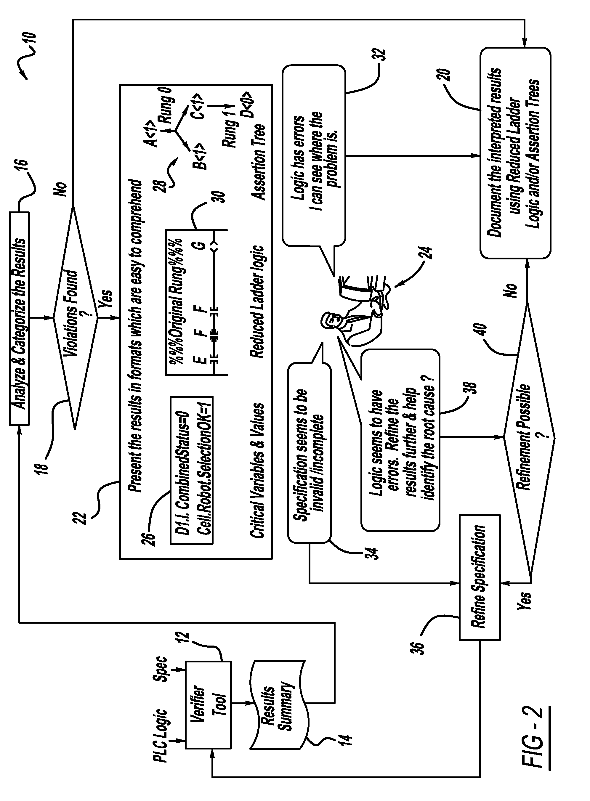
[0011]In accordance with the teachings of the present invention, a system and method are disclosed for interpreting formal verification results of PLC logic code used to control a manufacturing process, or other automated process, where the interpretation process does not require highly skilled technicians having significant experience in computer and mathematical algorithms. The verification process includes mathematically modeling the PLC logic code, mathematically formulating the expected behavior of the logic code and providing a verification results summary to check the compliance of the code with respect to the specifications. The verification results summary is analyzed and categorized to determine whether violations or errors are found in the results. The results can be depicted by assertion trees if a direct assertion between the PLC logic and the specifications can be provided. Alternatively, the results can be depicted by a reduced ladder logic if a direct assertion between the PLC logic and the specifications cannot be provided and a simulation is required. Once the result interpretation is completed, an operator is guided by the framework to refine the specification to a level where the specification adequately represents the reality or expected behavior of the process and against which the PLC logic code verification can be performed or the verification results can be documented.

Problems solved by technology

It is understood in the art that using prototype test case based methods or simulation based methods for verifying a manufacturing process typically do not allow for testing of all scenarios to check the compliance of the PLC code.
Because the testing is not exhaustive or complete, there is a possibility that the PLC code can be successfully passed with the limited testing scenarios, but still includes errors.
However, these types of PLC logic verification processes employing mathematical models and algorithms have typically required highly skilled operators to interpret the results.

Method used


Image

  • Framework for results interpretation and guided refinement of specifications for PLC logic verification
  • Framework for results interpretation and guided refinement of specifications for PLC logic verification
  • Framework for results interpretation and guided refinement of specifications for PLC logic verification

Examples


Embodiment Construction

[0023]The following discussion of the embodiments of the invention directed to a system and method for providing PLC logic verification of an assembly or manufacturing process is merely exemplary in nature, and is in no way intended to limit the invention or its applications or uses. For example, the present invention has particular application for assembly and manufacturing processes for automotive applications. However, as will be appreciated by those skilled in the art, the system and method for providing PLC logic verification of the invention will have application for many other types of processes.

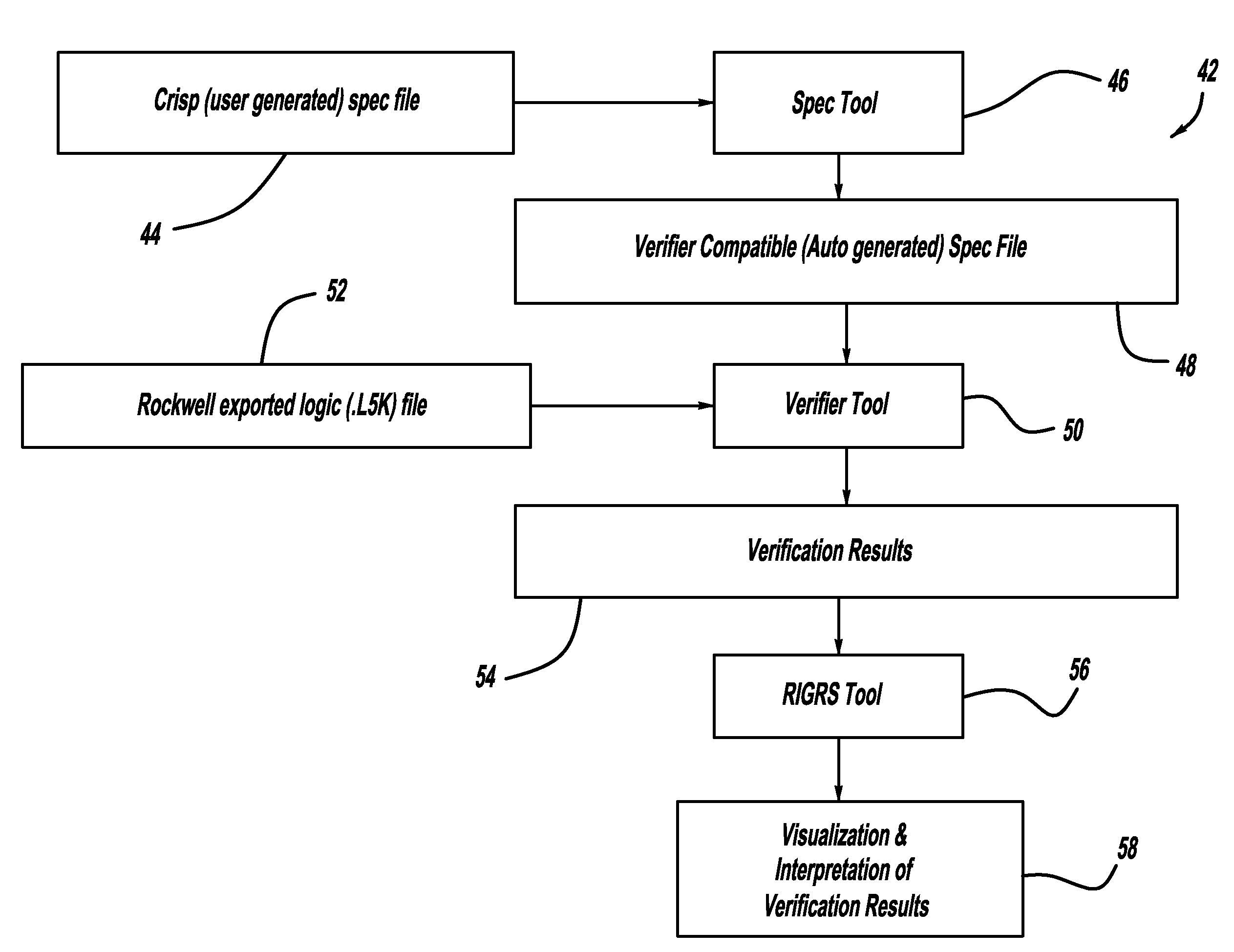
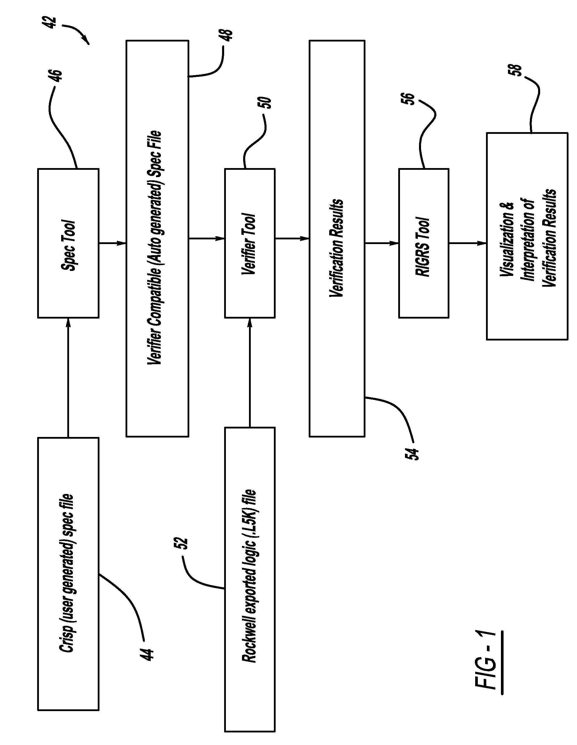
[0024]FIG. 1 is a flow chart diagram 42 showing the overall method for conducting formal verification of PLC logic in a manufacturing process, including a framework for a results interpretation and guided refinement of specifications. A user generates a specification file at box 44, sometimes referred to as a crisp file, and loads it into a specification tool at box 46. This type of s...


PUM


Abstract

A system and method for interpreting formal verification results of PLC logic code used to control a manufacturing process, or other automated process, where the interpretation process does not require highly skilled technicians having significant experience in computer and mathematical algorithms. The verification process includes providing a verification results summary to check the compliance of the code with respect to the specifications. The verification results summary is analyzed and categorized to determine whether violations or errors are found in the results. The results can be depicted by assertion trees if a direct assertion between the PLC logic and the specifications can be provided. Alternatively, the results can be depicted by a reduced ladder logic if a direct assertion between the PLC logic and the specifications cannot be provided and a simulation is required. The specification refinement suggestions will be provided if the critical variable for violations is identified.

Description

CROSS-REFERENCE TO RELATED APPLICATIONS[0001]This application claims the benefit of the filing date of U.S. Provisional Application Ser. No. 61 / 020,865 filed Jan. 14, 2008.BACKGROUND OF THE INVENTION[0002]1. Field of the Invention[0003]This invention relates generally to a system and method for providing a formal verification of programmable logic controller (PLC) logic code and, more particularly, to a system and method for providing a formal verification of PLC logic code for a manufacturing process where the verification results are presented in a format readily understandable by control engineers who may not have formal methods background.[0004]2. Discussion of the Related Art[0005]PLCs are modern industrial controllers that include hardware and software customized for industrial environments, such as manufacturing plants. The software, normally referred as the PLC logic code, which controls the PLC and industrial environments, is critical for controlling the operation of the pl...

Claims


Application Information

Patent Timeline
Patent Type & Authority Applications(United States)
IPC IPC(8): G05B19/42G06F17/10
CPCG05B19/058G05B2219/13188G05B2219/13151
Inventor SETHURAMAN, NAGARAJANDE, SOUMENYUAN, CHENGYINHUNSUR, NARAHARI K.
Owner GM GLOBAL TECH OPERATIONS LLC
Learn More