Method for controlling a quantity of water to be used for the purpose of obtaining a quantity of hot liquid

a technology of hot liquid and quantity, applied in the field of quantity control, can solve the problem of method that requires the application of rather expensive components in the coffee maker, and achieve the effect of high accuracy in the quantity control process

Inactive Publication Date: 2009-07-23
KONINKLIJKE PHILIPS ELECTRONICS NV
View PDF8 Cites 8 Cited by
  • Summary
  • Abstract
  • Description
  • Claims
  • Application Information

AI Technical Summary

Benefits of technology

[0008]On the one hand, the above-described known methods of controlling a quantity of water that is used in a process of preparing coffee may yield good results, but, on the other hand, these methods require an application of rather expensive components in a coffee maker. Therefore, it is an objective of the present invention to provide a method of controlling a quantity of water to be used for the purpose of obtaining a quantity of hot liquid, which offers a possibility of avoiding the application of expensive components. The objective is achieved by a method which comprises the following steps:
[0014]The method according to the present invention is applicable in case cold water enters the boiler through the water inlet of the boiler when hot water is pumped out of the boiler. In such case, due to the fact that a density of cold water is higher than a density of hot water, there is a separation layer which separates the cold water from the hot water. When the separation layer reaches the position where the temperature of the water is measured, a sudden decrease of the temperature is detected, wherein the temperature changes from a value above a predetermined value to below this predetermined value. At that instant, or a predetermined period of time later, the water flow is stopped, and the quantity of hot water that is pumped out of the boiler corresponds to the quantity of cold water that has entered the boiler during the pumping action. This quantity has a consistent value, provided that the measurements of the temperature of the water are performed at the same level with respect to the water inlet of the boiler. In view of the fact that there is a considerable difference between the temperature of the cold water and the temperature of the hot water, which may even be larger than 70° C., it is possible to accurately determine the moment at which the water flow needs to be stopped.
[0024]It is noted that the combination of the switching device and the sensing member may be a relatively cheap mechanical thermostat or any other commercially available suitable component.
[0028]In a particular embodiment, the device according to the present invention comprises a push button switch for temporarily closing the pumping circuit, and a relay which is arranged in the pumping circuit. The relay may be an electromechanical relay, for example. In this embodiment of the device, a user determines the moment at which a pumping action is initiated, namely by operating the push button switch. The arrangement of the relay in the energizing circuit of the device may be such that a coil of the relay is self-energized, so that the pump is kept running even when the user releases the push button of the push button switch. When the pumping action is terminated, the supply of current to the coil of the relay is interrupted. In this embodiment, the heating circuit may be automatically closed when the temperature of the water inside the boiler is lower than a predetermined level, and a process of energizing the heating means of the boiler may be automatically resumed, without intervention of the user.

Problems solved by technology

On the one hand, the above-described known methods of controlling a quantity of water that is used in a process of preparing coffee may yield good results, but, on the other hand, these methods require an application of rather expensive components in a coffee maker.

Method used


Image

  • Method for controlling a quantity of water to be used for the purpose of obtaining a quantity of hot liquid
  • Method for controlling a quantity of water to be used for the purpose of obtaining a quantity of hot liquid
  • Method for controlling a quantity of water to be used for the purpose of obtaining a quantity of hot liquid

Examples


Embodiment Construction

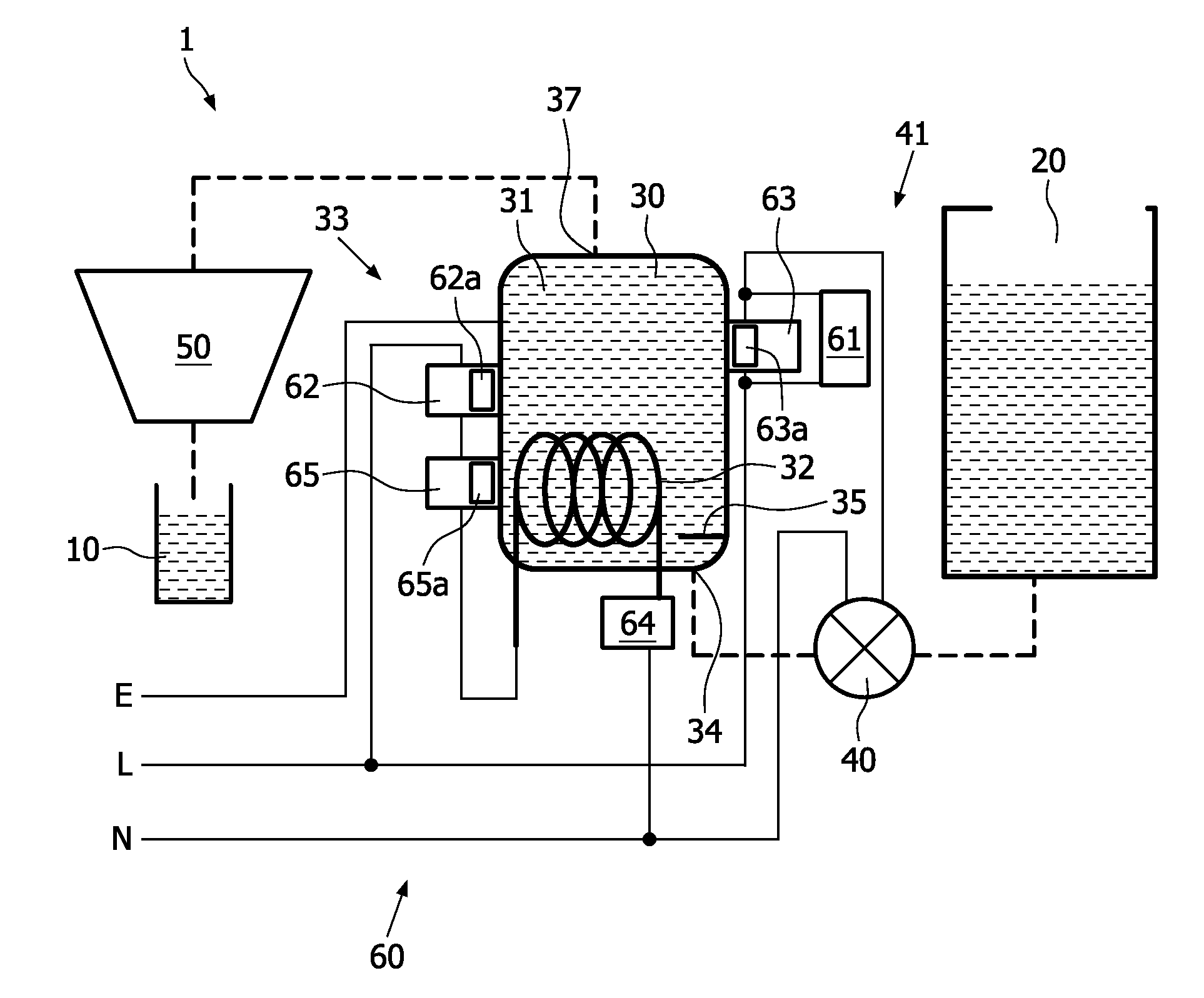
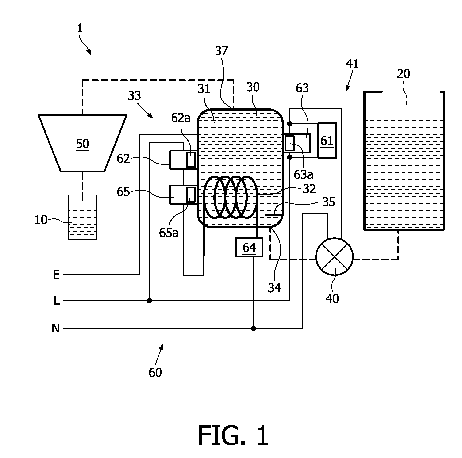
[0037]FIG. 1 diagrammatically shows components 20, 30, 40, 50 and an electric circuit 60 of a beverage maker 1 according to a first preferred embodiment of the present invention, which will hereinafter be referred to as first beverage maker 1. This beverage maker 1 is suitable for making coffee on the basis of hot water and a coffee pad (not shown) filled with ground coffee beans, which does not alter the fact that the beverage maker 1 may just as well be suitable for preparing other hot drinks. Besides the components 20, 30, 40, 50 and the electric circuit 60 of the first beverage maker 1, FIG. 1 also shows a container 10 such as a cup for receiving the coffee from the beverage maker 1.

[0038]The first beverage maker 1 comprises a water tank 20 for containing water, a boiler 30 having an interior space 31 for containing water and a heating element 32 for supplying heat to the water, an electric pump 40 for pumping water from the water tank 20 to the boiler 30, and a sealable brew ch...


PUM


Abstract

A beverage maker (1) comprises a boiler (30) for containing and heating water and a normally opened thermostat (63) having a sensing member (63a) for sensing a temperature of the water, wherein the sensing member (63a) is located at a certain distance with respect to a water inlet (34) of the boiler (30). When the water is heated, and the temperature of the water exceeds a set point of the thermostat (63), the thermostat (63) closes. As a result, a pumping action is started, wherein hot water is forced to flow out of the boiler (30), and wherein cold water is forced to flow into the boiler (30). When a front of the cold water reaches the sensing member (63a) of the thermostat (63), the thermostat (63) is triggered to open again, and the pumping action is terminated. By means of the thermostat (63), the quantity of hot water that is used for the purpose of making a beverage is accurately controlled.

Description

FIELD OF THE INVENTION[0001]The present invention relates to a method for controlling a quantity of water to be used for the purpose of obtaining a quantity of hot liquid, and to a device which is adapted to carrying out this method. Among other things, the method according to the present invention is applicable in the field of controlling a quantity of water to be used in a process of preparing a hot beverage.BACKGROUND OF THE INVENTION[0002]In a process of preparing a hot beverage, both a temperature of the water and a quantity of the water in relation to a quantity of extractable material are important factors. This is particularly true in the case of a process of preparing coffee on the basis of a quantity of ground coffee beans and hot water. In such a case, a proportion between the quantity of ground coffee beans and a quantity of hot water that is conducted through the ground coffee beans is determinative of the strength and aroma of the coffee.[0003]Usually, coffee is prepar...

Claims


Application Information

Patent Timeline
Patent Type & Authority Applications(United States)
IPC IPC(8): A47J31/40A47J31/56
CPCA47J31/56A47J31/402F24H1/08F24H9/2007
Inventor QUAH, PENG CHAUWESTRA, THEWIS M.DE HAAN, THIJSBOSSTAD, PIETER BERENDBLEEKER, JEAN BART
Owner KONINKLIJKE PHILIPS ELECTRONICS NV
Why Eureka
Try Eureka