Connector for a fluid tank

Active Publication Date: 2009-07-23
SURPASS IND
View PDF14 Cites 5 Cited by
  • Summary
  • Abstract
  • Description
  • Claims
  • Application Information

AI Technical Summary

Benefits of technology

[0007]In consideration of the circumstances described above, one object of the present invention to provide a fluid tank connector that enables the reliable execution of the separation of the plug and the socket by opposing the coupling force of the fluid sealing portion.
[0011]Moreover, preferably, the pressing means are provided in the socket. It is thereby possible to simplify the structure of the plug.
[0013]There are cases in which, for various reasons, a user may wish to remove a plug from the fluid port of the fluid tank. In these cases, preferably, the plug is fit with play into the fluid port. Even when the plug is fit with play into the fluid port in this manner, it is possible to reliably separate the plug from the socket by using the pressing means, and thus, it is possible to avoid removing the plug from the fluid tank connected to the socket.
[0015]The replaceable sealing member is provided on the socket side as a gas sealing portion. By replacing the sealing member, it is possible to maintain the gas sealing portion over a long period of time. In particular, because it is often the case that the socket is connected and attached to a facility side that supplies a fluid and frequent replacement cannot be carried out, it is possible to improve the serviceability by providing a replaceable sealing member in advance at the socket side.
[0017]According to the present invention, because pressing means are provided that separate the plug by opposing (overcoming) the coupling force of the fluid sealing portion, when the socket is removed from the plug, it is possible to reliably separate the socket from the plug while the plug continues to remain disposed on the fluid tank side.

Problems solved by technology

In the case in which the coupling force (frictional force) of the fluid sealing portion that is provided between the plug and the socket is strong, when the socket is to be separated from the plug, there is a concern that the connection between the plug and the socket will not be released and that the socket and the plug will both be removed from the fluid port of the fluid tank.

Method used


Image

  • Connector for a fluid tank
  • Connector for a fluid tank
  • Connector for a fluid tank

Examples


Embodiment Construction

[0027]An embodiment of the fluid tank connector according to the present invention will be explained with reference to the drawings.

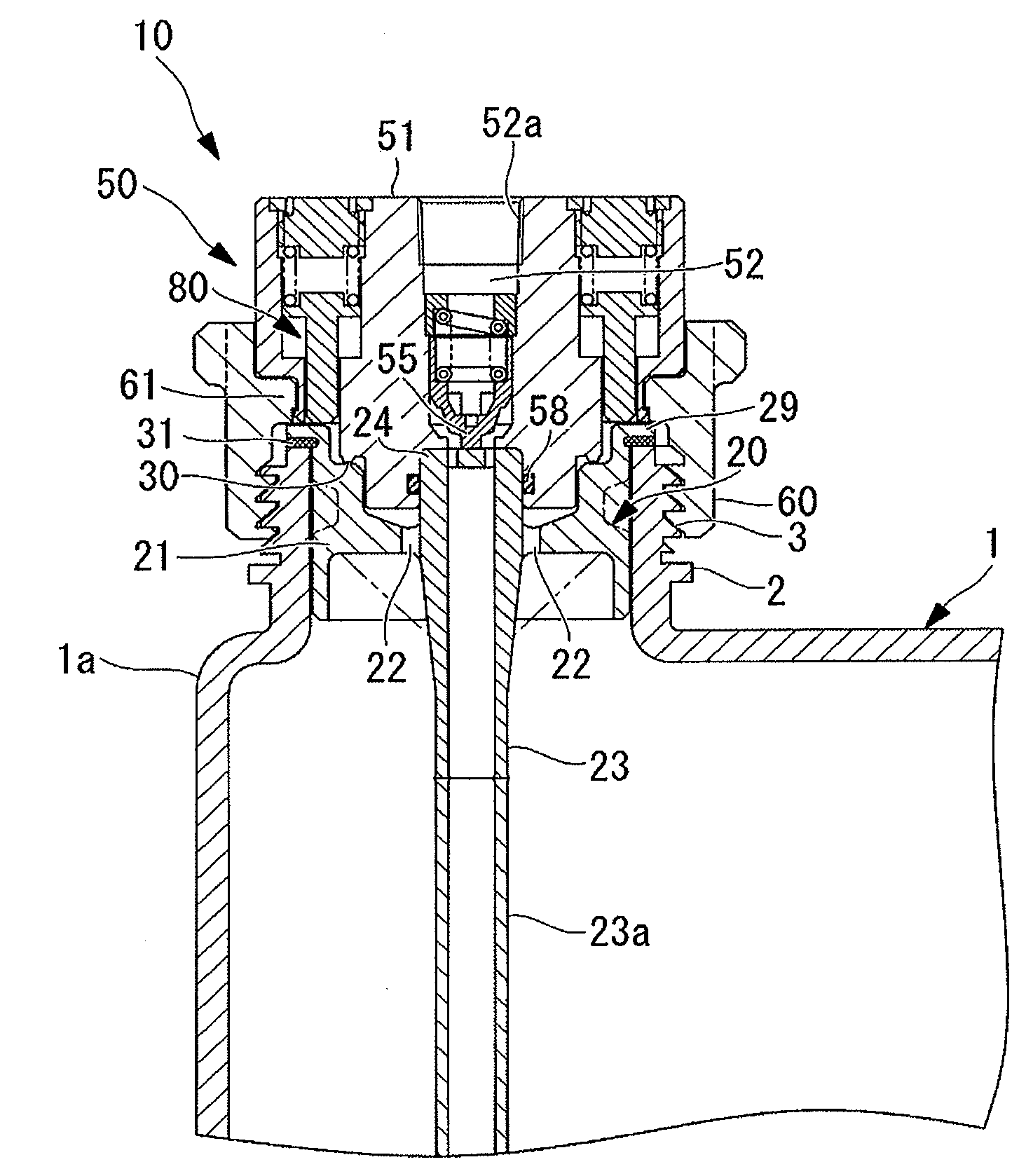
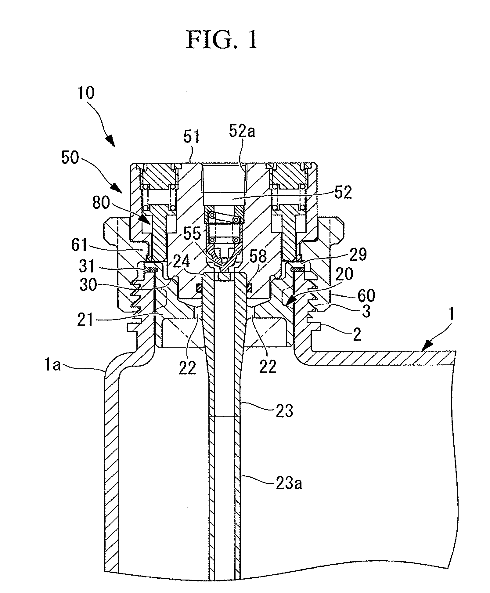
[0028]FIG. 1 shows a fluid tank connector 10 that is installed in a fluid port 2 of a fluid tank 1. The fluid tank connector 10 is provided with a plug 20 that is accommodated inside the fluid port 2 and a socket 50 that is detachably connectable to the plug 20. The fluid tank connector 10 uses a siphon hose method, in which, in order to remove the fluid that is stored inside the fluid tank 1, a gas, such as air, is introduced to the inside of the fluid tank 1 and the fluid is fed to the outside of the fluid tank 1 due to the gas pressure that is produced thereby.

[0029]The fluid tank 1 that has been filled with a chemical fluid (fluid), such as a high-purity chemical product for semiconductors, is a molded product made, for example, of a chemical-resistant resin. The fluid port 2, which is provided at the top of the fluid tank 1, is an open portion that...


PUM


Abstract

A fluid tank connector enables reliable separation of a plug and a socket by opposing the coupling force of a fluid sealing portion. The fluid tank connector is provided with a plug that is fit with play in the inner periphery of a fluid port of the fluid tank that stores a fluid, and a socket that is detachably connectable to the plug. The socket includes a sleeve that connects and disconnects the socket and the plug by being threadable on an external thread that is formed on the outer periphery of the fluid port. A pressing means is provided in the socket, and the pressing means applies a pressing force that separates the plug from the socket by opposing the coupling force of an 0-ring that seals the fluid path between the plug and the socket.

Description

CROSS REFERENCE TO RELATED APPLICATIONS[0001]This application claims priority to Japanese Patent Application No. 2008-010934 filed on Jan. 21, 2008, the contents of which are incorporated herein by reference.FIELD OF THE INVENTION[0002]The present invention relates to a fluid tank connector for delivering a fluid that is inside a fluid tank to the outside thereof.BACKGROUND OF THE INVENTION[0003]Generally, fluids such as high-purity chemical products for semiconductors or general-use chemical products are filled into fluid tanks such as polyethylene tanks at a production facility, and they are shipped after a lid has been attached to a fluid port for filling and discharging that is formed in this fluid tank. As a method for removing the fluid that has been stored in such a fluid tank, a siphon hose method is known in which a gas such as air is introduced into the container, and the fluid is fed to the outside of the container due to the gas pressure that is produced thereby.[0004]In...

Claims


Application Information

Patent Timeline
IPC IPC(8): B65D51/00
CPCB65D51/1683Y10T137/314A41D13/08A41D19/0017A41D2400/26A41D2600/10
Inventor TAKANOHASHI, TOSHIYUKI
Owner SURPASS IND
Why Eureka
Try Eureka