Method and apparatus for aerial fuel transfer

Active Publication Date: 2009-07-23
THE BOEING CO
View PDF5 Cites 16 Cited by
  • Summary
  • Abstract
  • Description
  • Claims
  • Application Information

AI Technical Summary

Benefits of technology

[0013]The advantageous embodiments provide a method and apparatus for refueling an aircraft. In one advantageous embodiment, a refueling duct is deployed from an aft position of the aircraft while the aircraft is flying, wherein the refueling duct comprises a hose and a controllable drogue. The refueling duct is positioned through c

Problems solved by technology

A series of air refuelings may provide a range that is limited only by crew fatigue and maintenance factors, such as engine oil consumption.
If the speed is too high, damage may occur to the probe or drogue.
If an approach by a pilot of a receiving aircraft to

Method used


Image

  • Method and apparatus for aerial fuel transfer
  • Method and apparatus for aerial fuel transfer
  • Method and apparatus for aerial fuel transfer

Examples


Embodiment Construction

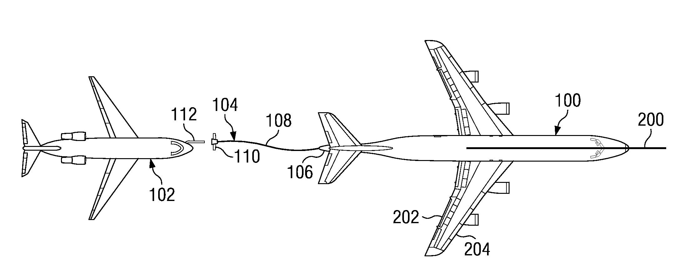
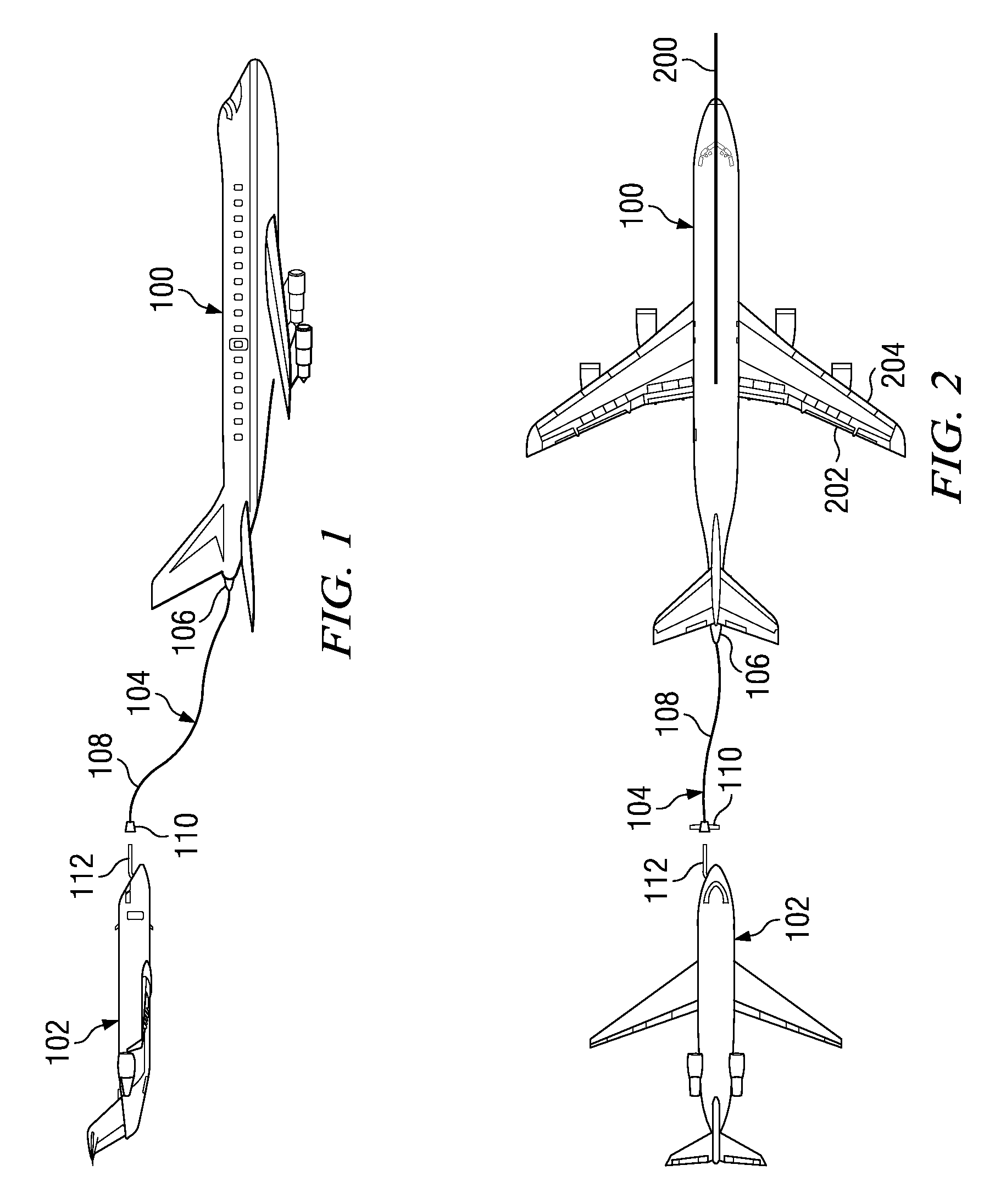
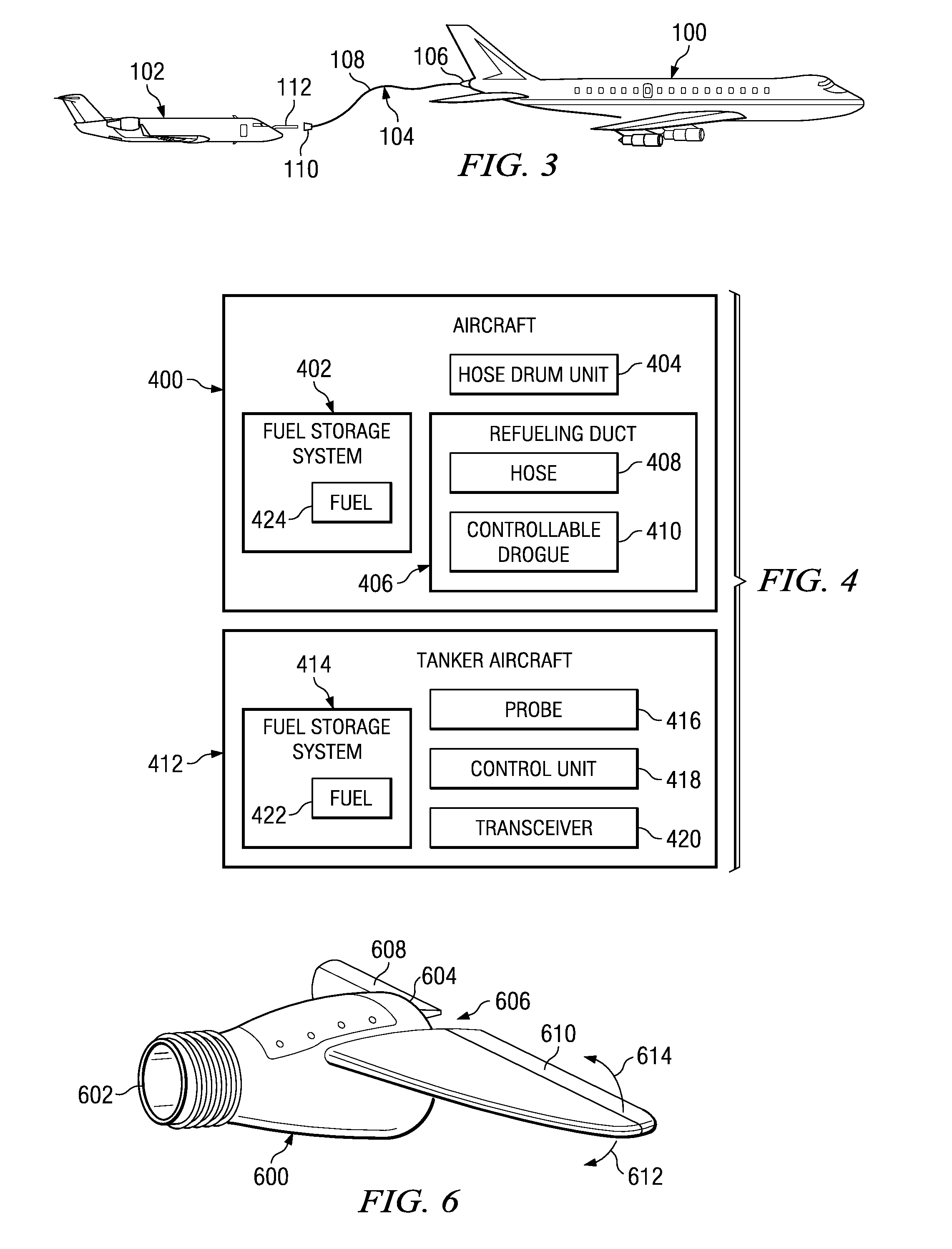
[0026]With reference now to the figures and in particular with reference to FIG. 1, a diagram illustrating two aircraft used in a refueling process is depicted in accordance with an advantageous embodiment. In this example, aircraft 100 is a refueling aircraft that is to receive fuel. Tanker aircraft 102 is a source of fuel for aircraft 100.

[0027]In this example, aircraft 100 has refueling duct 104, which trails from aft position 106 of aircraft 100. Refueling duct 104 takes the form of hose 108 and drogue 110. Tanker aircraft 102 includes probe 112. This probe also may be referred to as a stinger and is capable of coupling with drogue 110. In this example, tanker aircraft 102 is located behind aircraft 100 for the refueling process. Tanker aircraft 102 is located above aircraft 100 as well as being behind aircraft 100. By being located above aircraft 100, pumping or transferring fuel from tanker aircraft 102 to aircraft 100 is achieved using less horsepower in the pumping equipment...


PUM


Abstract

A method and apparatus for transferring fuel onto or off of an aircraft. A refueling transfer duct is deployed from an aft station of the aircraft being serviced while the aircraft is flying, wherein the transfer apparatus comprises a hose with a controllable drogue attached to its free end. The refueling duct is positioned through control signals sent by a tanker aircraft to the controllable drogue to form a favorably positioned refueling duct capable of a finite final docking maneuver. The positioned refueling duct is connected to the tanker aircraft positioned behind the aircraft to form a connection. The fuel is transferred through the connection to a fuel tank or fuel storage system located within the aircraft.

Description

BACKGROUND INFORMATION[0001]1. Field[0002]The present disclosure relates generally to aircraft and in particular to refueling aircraft. Still more particularly, the present disclosure relates to a method and apparatus for moving fuel between two aircraft during flight.[0003]2. Background[0004]Air refueling is a process of transferring fuel from one aircraft to another aircraft during flight. A tanker aircraft is the aircraft that typically provides fuel to another aircraft. The aircraft receiving fuel is referred to as a refueling aircraft. This process allows the aircraft receiving fuel to remain in flight for longer periods of time. As a result, an aircraft may extend its range through this type of process. A series of air refuelings may provide a range that is limited only by crew fatigue and maintenance factors, such as engine oil consumption.[0005]Further, when an aircraft can receive extra fuel in the air, the aircraft can takeoff with a greater payload, such as weapons, cargo...

Claims


Application Information

Patent Timeline
IPC IPC(8): B64D39/00
CPCB64D39/00
Inventor MATHENY, WILLIAM FRANCIS
Owner THE BOEING CO
Why Eureka
Try Eureka