Bidirectional Sealing Mechanically Shifted Ball Valve for Downhole Use

Active Publication Date: 2009-07-23
BAKER HUGHES INC
View PDF39 Cites 32 Cited by
  • Summary
  • Abstract
  • Description
  • Claims
  • Application Information

AI Technical Summary

Benefits of technology

[0007]A downhole ball valve is mounted n a string and features a rotating ball that turns on its axis as it is held against an upstream and a downstream seal by a cage. The cage accepts a slide that engages the ball off-center to rotate it between the open and closed positions. A sleeve is attached to a piston assembly which in turn is attached to the slide for tandem movement to rotate

Problems solved by technology

These surface lubricators have limited lengths dete

Method used


Image

  • Bidirectional Sealing Mechanically Shifted Ball Valve for Downhole Use
  • Bidirectional Sealing Mechanically Shifted Ball Valve for Downhole Use
  • Bidirectional Sealing Mechanically Shifted Ball Valve for Downhole Use

Examples


Embodiment Construction

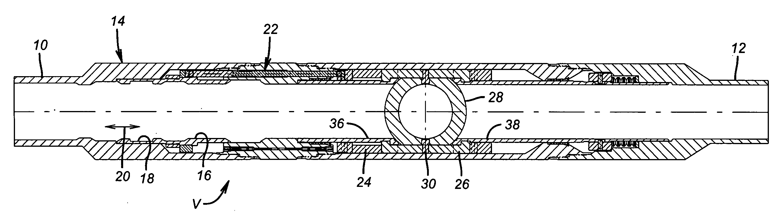
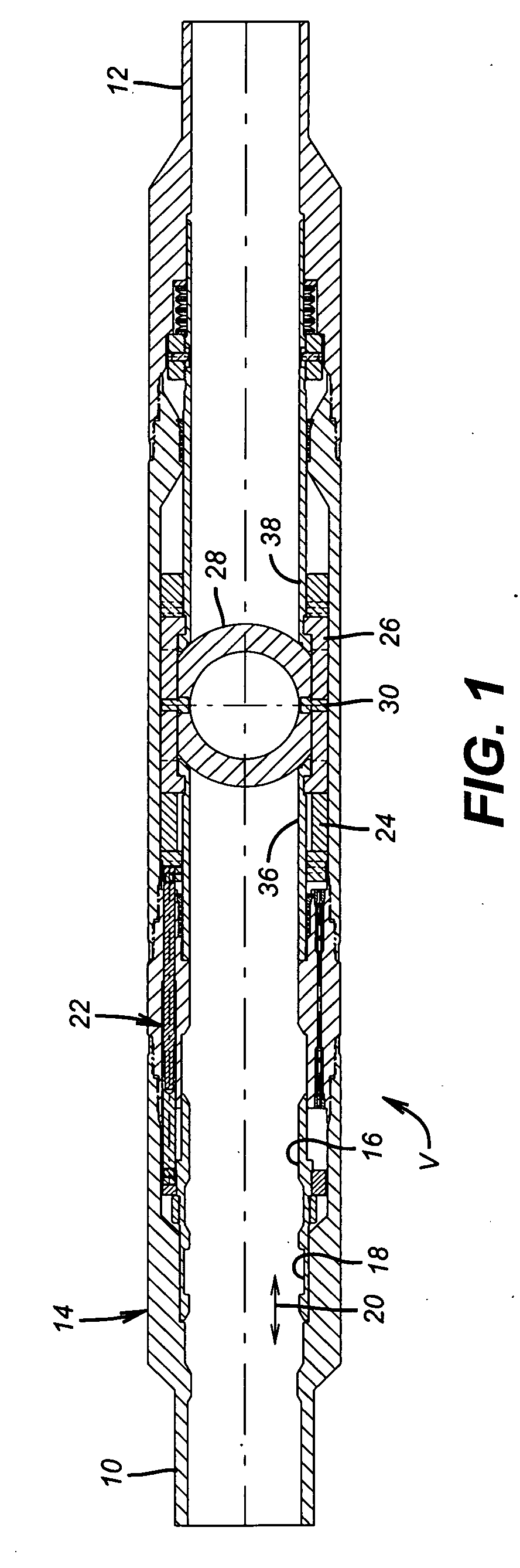
[0013]Referring to FIGS. 1 and 5, the valve V is part of a string (not shown) that goes downhole and is connected to the top end 10 and the bottom end 12 of the housing 14. An inner sleeve 16 has an internal groove 18 to be engaged and moved in opposed directions preferably by a wireline tool represented schematically by double headed arrow 20. Movement of sleeve 16 shifts the piston assembly 22 and with it slide 24 relative to stationary cage 26. Ball 28 is pinned with opposed pins 30 so that it can rotate about them on its central axis. Pins 32 extend from arms 34 and engage ball 28 off-center so as to be able to rotate ball 28 in opposed directions when the slide 24 moves with respect to the stationary cage 26. Upper seat 36 and lower seat 34 are retained to the ball 28 with the cage 26.

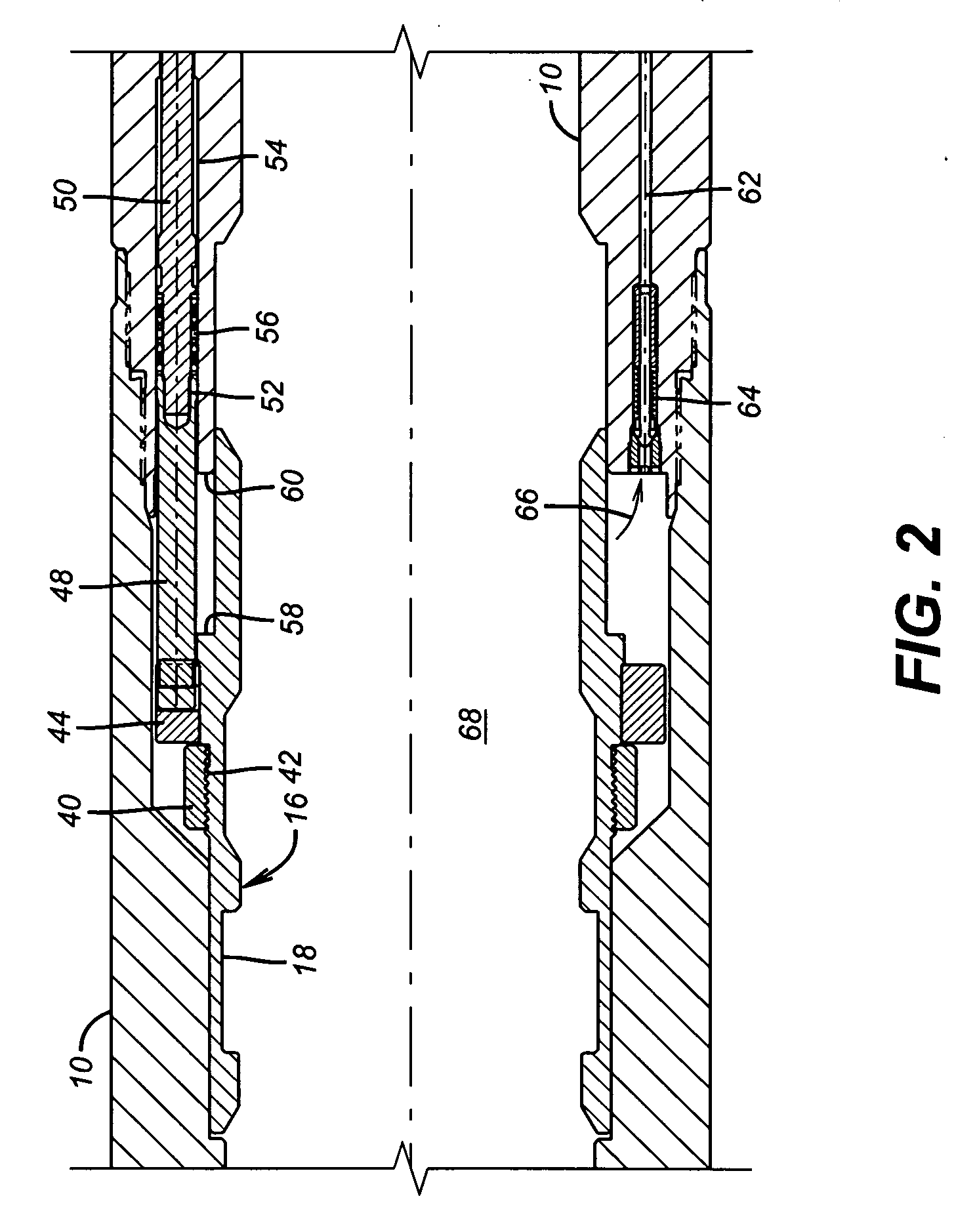
[0014]With the major components now described, a detailed description of the remaining components will be more readily understood using the enlarged views of FIGS. 2-4. Sleeve 16 has a retaining n...


PUM


Abstract

A downhole ball valve is mounted n a string and features a rotating ball that turns on its axis as it is held against an upstream and a downstream seal by a cage. The cage accepts a slide that engages the ball off-center to rotate it between the open and closed positions. The slide is operated by a sleeve attached to a piston assembly. The sleeve is mechanically operated in opposed directions such as by a wireline shifting tool. Differential pressure on a closed ball does not affect the actuation piston because pressure across the actuating piston is balanced while holding pressure differential across the closed ball. A check valve allows the actuation piston to be in pressure balance as the ball stays closed.

Description

PRIORITY INFORMATION [0001]This application is a continuation in part of Application Ser. No. 11 / 595,596 filed Nov. 9, 2006 entitled Downhole Lubricator Valve.FIELD OF THE INVENTION[0002]The field of the invention relates to downhole shutoff valves, that can be used in a lubricator application, that allow a string to be made up in a live well by isolation of a lower portion of it and more particularly to features regarding such valves relating to mechanically operating them and design features that prevent applied differential pressure from above to inadvertently open them.BACKGROUND OF THE INVENTION[0003]Lubricator valves are valves used downhole to allow long assemblies to be put together in the well above the closed lubricator valve with well pressure further below the closed lubricator valve. These valves are frequently used in tandem with sub-surface safety valves to have redundancy of closures against well pressures below.[0004]Lubricator assemblies are used at the surface of...

Claims


Application Information

Patent Timeline
IPC IPC(8): F16K5/06
CPCE21B2034/002E21B34/14E21B2200/04F16K11/056
Inventor BEALL, CLIFFORD H.SLOAN, JAMES T.PATTERSON, RICHARD
Owner BAKER HUGHES INC
Why Eureka
Try Eureka