
Automatic workpiece clamp and support

Inactive Publication Date: 2009-07-23
WUERTHNER MATTHEW WAYNE
View PDF2 Cites 8 Cited by
  • Summary
  • Abstract
  • Description
  • Claims
  • Application Information

AI Technical Summary

Benefits of technology

[0007]The invention has an open slot at the top through which a planar workpiece is inserted. As the workpiece is lowered, it engages a flexible strap which is attached on either end to rigid bars with a substantially square cross-section. These rigid bars serve as clamping jaws. The weight of the workpiece forces the clamping jaws together, overcoming the force of a spring or other elastic mechanism that keeps the jaws separate when no workpiece is engaged. The spring mechanism keeps the clamping jaws separated in an open position via rotating levers that are attached to the spring, the frame and the top portions of the clamping jaws. On the lower portions of the clamping jaws there are pivoting arms which attach to the frame portion of the invention. As these pivoting arms are rigid with respect to any horizontal movement perpendicular to the clamping motion, they serve as an effective means of preventing the clamping jaws from swinging while engaged.
[0008]All parts comprising the top of the invention are beveled so that it may be used to hold the broad side of a workpiece at an acute angle with respect to the ground. Upon the placement of a sufficiently heavy workpiece, such as a door, on top of the invention, the weight of the workpiece forces the top levers down into a position that is parallel to the ground. All top portions are beveled so that when the levers swing to this parallel position they form a continuous smooth angle allowing for stable support of a door when laid at a sufficiently acute angle with respect to the ground.
[0009]To prevent the invention from falling over while in use, it is equipped with a rotating leg piece that swings out laterally on both sides of the frame base.

Problems solved by technology

Although this latter type of mechanism permits automatic clamping, all such devices employing it to date are composed of numerous parts and contain several points of friction between the receiver and the clamping mechanism.

Method used


Image

  • Automatic workpiece clamp and support
  • Automatic workpiece clamp and support
  • Automatic workpiece clamp and support

Examples


Embodiment Construction

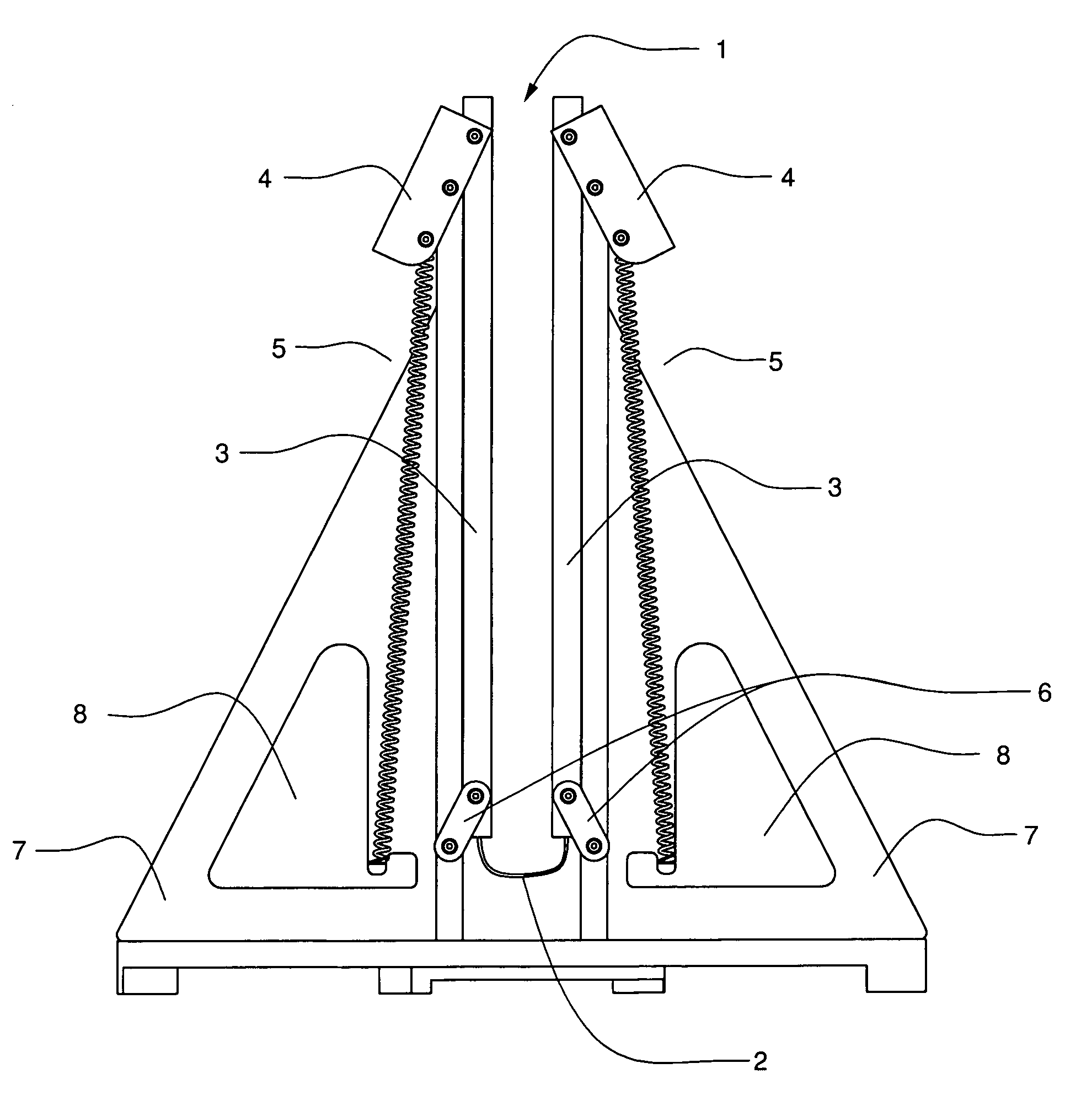
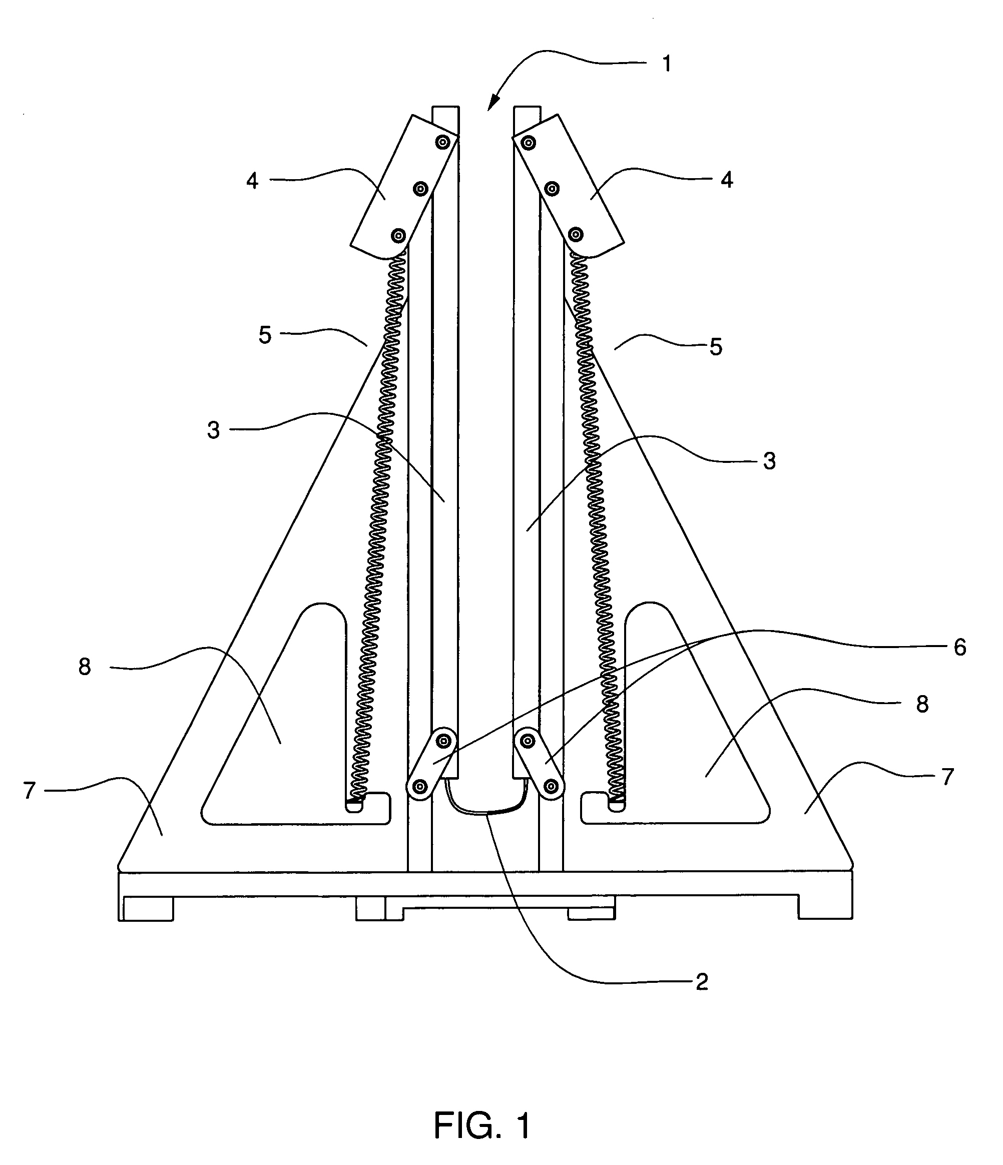
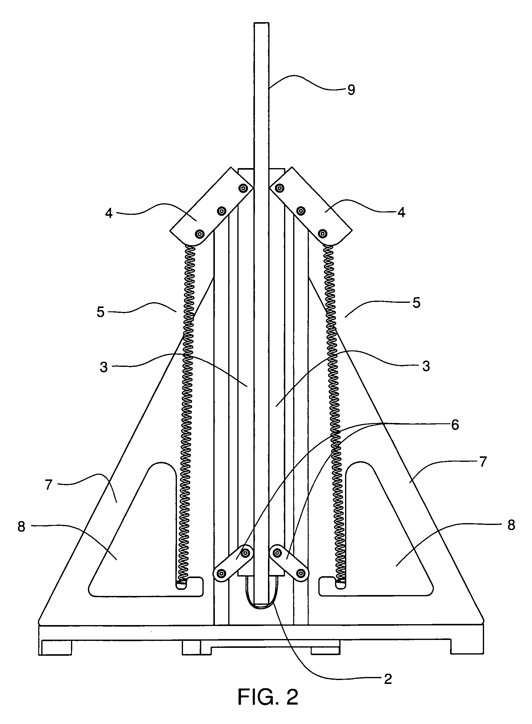
[0014]Before engagement with a workpiece, as shown in FIG. 1, the clamping jaws 3 are pressed against the frame 7 by springs or other elastic members 5 which are connected to the clamping jaws 3 via rotating levers 4 that are secured to the frame 7. The point at which the levers 4 join the frame 7 defines the pivot point for the levers. Before engagement, there is a gap 1 between the clamping jaws 3 into which a door, panel, window, plasterboard, or other workpiece can be inserted. The overall shape of the frame 7 is generally triangular and gap 1 essentially creates two symmetrical triangles on either side of the gap. Assuming the invention is composed of a sufficiently sturdy material such as wood, the centers of these two symmetrical triangles may be cut out 8 while preserving physical integrity. These cut outs 8 serve not only to lessen the overall weight of the invention, but also provide a simple and effective means for gripping it.

[0015]The design of the clamping jaws is crit...


PUM


Abstract

An automatic clamping device is disclosed for holding planar workpieces such as: doors, windows, panels, plasterboard, etc. The planar workpiece is held in an upright position by clamping jaws actuated by the weight of the workpiece. Automatic clamping is accomplished by placing the workpiece through a slot at the top of the clamping device and lowering it onto a flexible strap connected to movable jaws which, under the weight of the workpiece, move laterally towards and clamp the workpiece. The workpiece is released by simply lifting it up through the slot and coil springs will automatically return the jaws to an open position. The device also provides support for holding planar workpieces on an incline.

Description

BACKGROUND OF THE INVENTION[0001]1. Field of the Invention[0002]The invention relates generally to the quick engagement of planar workpieces in a steady upright position while work is done upon them and more specifically to the quick engagement and disengagement of a door, window, or plasterboard as such an objects is cut, trimmed, painted or prepared for lock and hinge installation.[0003]2. Description of the Prior Art[0004]There are numerous devices in the field of door holders and clamps dating back to the nineteenth century. These devices can be separated into two basic mechanisms. One type of mechanism uses a brace or a plurality of braces to hold the door or other planar piece on edge and the positioning of the braces is secured by either a wedge (U.S. Pat. No. 7,125,009), a screw (e.g. U.S. Pat. No. 6,886,821), a pin (e.g. U.S. Pat. No. 5,294,099), a retractable spring (e.g. U.S. Pat. No. 4,391,437), or fixed ridges (e.g. U.S. Pat. No. 2,621,687). Another type uses the weight...

Claims


Application Information

Patent Timeline
IPC IPC(8): B25B5/06B23Q3/06B25B11/00
CPCE04F21/0007E04F21/0023Y10S269/905
Inventor WUERTHNER, MATTHEW WAYNE
Owner WUERTHNER MATTHEW WAYNE
Features
  • Generate Ideas
  • Intellectual Property
  • Life Sciences
  • Materials
  • Tech Scout
  • Unparalleled Data Quality
  • Higher Quality Content
  • 60% Fewer Hallucinations
Learn More