Pipe pulling assembly

a technology of pipe puller and assembly, which is applied in the direction of manufacturing tools, soldering devices, auxillary welding devices, etc., can solve the problems of two large diameter pipes, pipes, and inability to meet the requirements of prior art, and achieve accurate, safe and quick alignment. , the effect of accurate alignmen

Inactive Publication Date: 2009-07-23
GONZALES JR MANUEL J +1
View PDF24 Cites 0 Cited by
  • Summary
  • Abstract
  • Description
  • Claims
  • Application Information

AI Technical Summary

Benefits of technology

[0012]The pipe pulling assembly (PPA) disclosed herein is designed to allow a single person to accurately, safely and quickly align, pull together and attach two large diameter pipes, such as water pipes having a diameter of 48-inches (1.22 meters). The PPA functions in combination with a first circular pipe having an outer diameter, an upper section and an integral lower section; and a second circular pipe having an inner diameter that is larger than the outer diameter of the first circular pipe, and an upper section and an integral lower section. The PPA also functions in combination with a first ratcheting tool that has attached a first ratchet hook and a second ratchet hook, and a second ratcheting tool that also has attached a first ratchet hook and a second ratchet hook.

Problems solved by technology

However, a tool to align and pull together two large diameter pipes, such as 48.0-inch (71.12 centimeter) water pipes, is not available in the prior art.
These large diameter pipes which can have a length of 20-feet (6.1 meters), are typically made of plastic such as PVC, are fragile and are at best difficult to align and to pull together.
The possibility of damaging at least one of the two pipes increases when utilizing the current method.
Additionally, the insertion length of the first pipe into the second pipe is limited to a small distance.
If this distance is exceeded, a fragile seal in the second pipe can be damaged which necessitates that the seal be repaired or replaced or if the damage is extensive the entire second pipe must be replaced.
A search of the prior art did not disclose any industry literature or patents that read directly on the claims of the instant invention.

Method used


Image

  • Pipe pulling assembly
  • Pipe pulling assembly
  • Pipe pulling assembly

Examples


Embodiment Construction

[0045]The best mode for carrying out the pipe pulling assembly is presented in terms of a preferred embodiment that allows two large diameter pipes to be accurately, safely and quickly connected together.

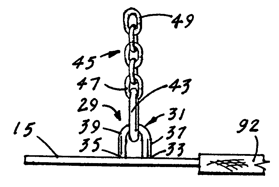
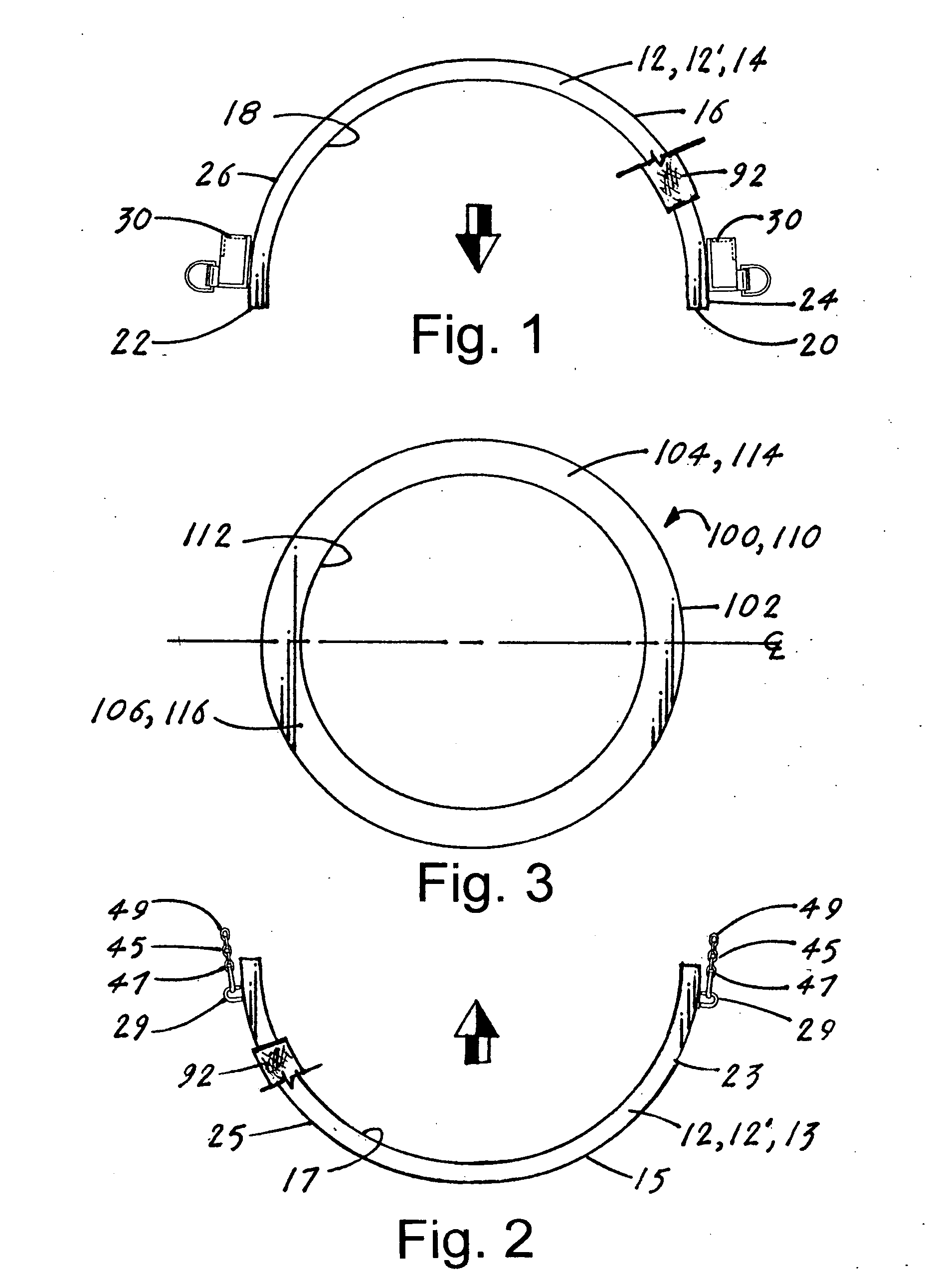
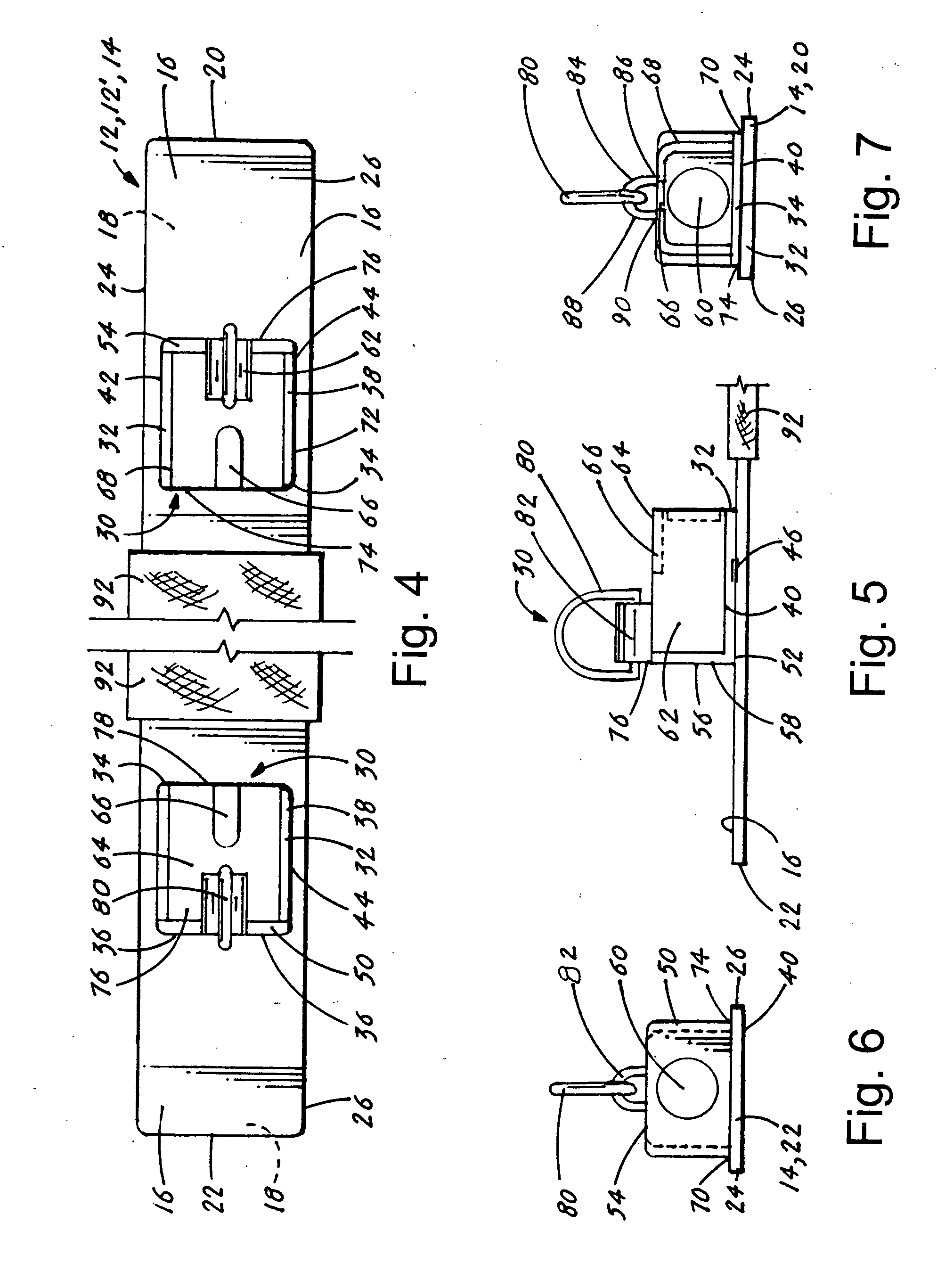
[0046]The preferred embodiment of the pipe pulling assembly 10 (hereinafter “PPA 10”), as shown in FIGS. 1-12, is comprised of a first circular band 12 and an identical second circular band 12′ that are designed to function in combination with a first circular pipe 100 and a second circular pipe 110. The first circular pipe 100 has an outer diameter 102, an upper section 104 and an integral lower section 106. The second circular pipe 110 has an inner diameter 112, an upper section 114 and an integral lower section 116. The inner diameter 112 on the second circular pipe 110 is larger than the outer diameter 102 of the first circular pipe 100 to allow the first circular pipe 100 to be inserted into and attached to the second circular pipe 110. The PPA 10 is particularly useful when at...


PUM


Abstract

A pipe pulling assembly (10) consisting of a first circular band (12) and an identical second circular band (12′). The two bands (12, 12′) are each comprised of an upper arcuate band (14) and a lower arcuate band (13) that are placed around the circumferential end of a first circular pipe (100) and a second circular pipe (110). Attached adjacent to the first and second end (20,22) of the upper arcuate band (14) is an upper band attachment structure (30) and attached adjacent to the first and second end (19,21) of the lower arcuate band (13) is a lower band attachment structure (29). A first ratcheting tool (118) is connected between the two structures (30,29) to cause the two structures (30,29) to close and tighten the two bands (14,13) around the first and second circular pipes (100,110). A second ratcheting tool (124) is then connected between the first and second upper band attachment structures (30) to cause the first circular pipe (100) to be pulled into and attached to the second circular pipe (110).

Description

TECHNICAL FIELD[0001]The invention pertains to the general field of pipe pullers, and more particularly to a pipe pulling assembly that utilizes a first circular band that is placed around the circumferential end of a first circular pipe and a second circular band that is placed over the circumferential end of a second pipe. The two circular bands are first tightened around their respective pipes by a first ratcheting tool. The two tightened bands are then connected and pulled inward by a second ratcheting tool that allows the two circular pipes to be accurately, safely and quickly connected.BACKGROUND ART[0002]A tool to align and pull a first circular pipe having an outer diameter into a second circular pipe having a larger diameter than the first pipe is available in the prior art. However, a tool to align and pull together two large diameter pipes, such as 48.0-inch (71.12 centimeter) water pipes, is not available in the prior art. These large diameter pipes which can have a leng...

Claims


Application Information

Patent Timeline
Patent Type & Authority Applications(United States)
IPC IPC(8): E21B19/06
CPCB23K37/0533
Inventor GONZALES, JR., MANUEL J.BORUNDA, ROBERTO M.
Owner GONZALES JR MANUEL J
Why Eureka
Try Eureka