Liquid ejecting apparatus

Active Publication Date: 2009-07-23
BROTHER KOGYO KK
View PDF3 Cites 9 Cited by
  • Summary
  • Abstract
  • Description
  • Claims
  • Application Information

AI Technical Summary

Benefits of technology

[0009]In the liquid ejecting apparatus constructed as described above, the two wipers are disposed so as to overlap each other as viewed in the second direction when each of the two wipers is located at the wiping complete position. Accordingly, it is possible to reduce a space, in terms of the first direction, occupied by the two wipers when each of the two wipers is located at the wiping complete position. Therefore, the liquid ejecting device can be downsi

Problems solved by technology

The arrangement inevitably increases the size of the device in te

Method used


Image

  • Liquid ejecting apparatus
  • Liquid ejecting apparatus
  • Liquid ejecting apparatus

Examples


Embodiment Construction

[0017]Referring to the drawings, there will be explained an ink-jet printer according to one embodiment. The ink-jet printer as a liquid ejecting apparatus is configured to record characters and images by ejecting ink as a liquid to a recording sheet as a recording medium.

1. Schematic Structure of Ink-Jet Printer

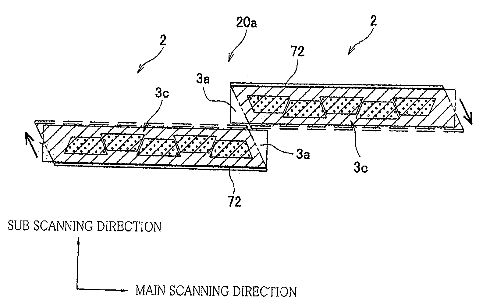
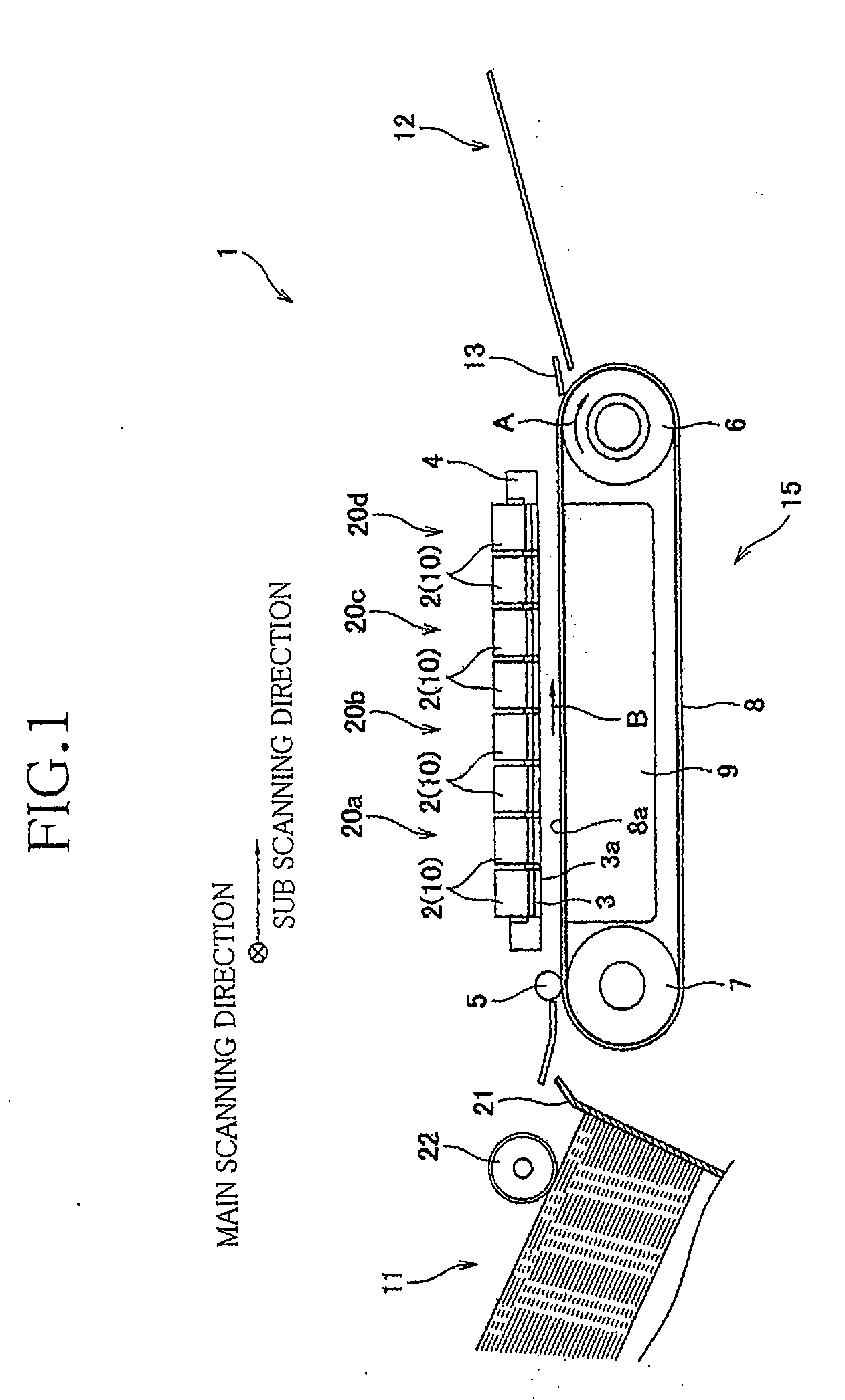
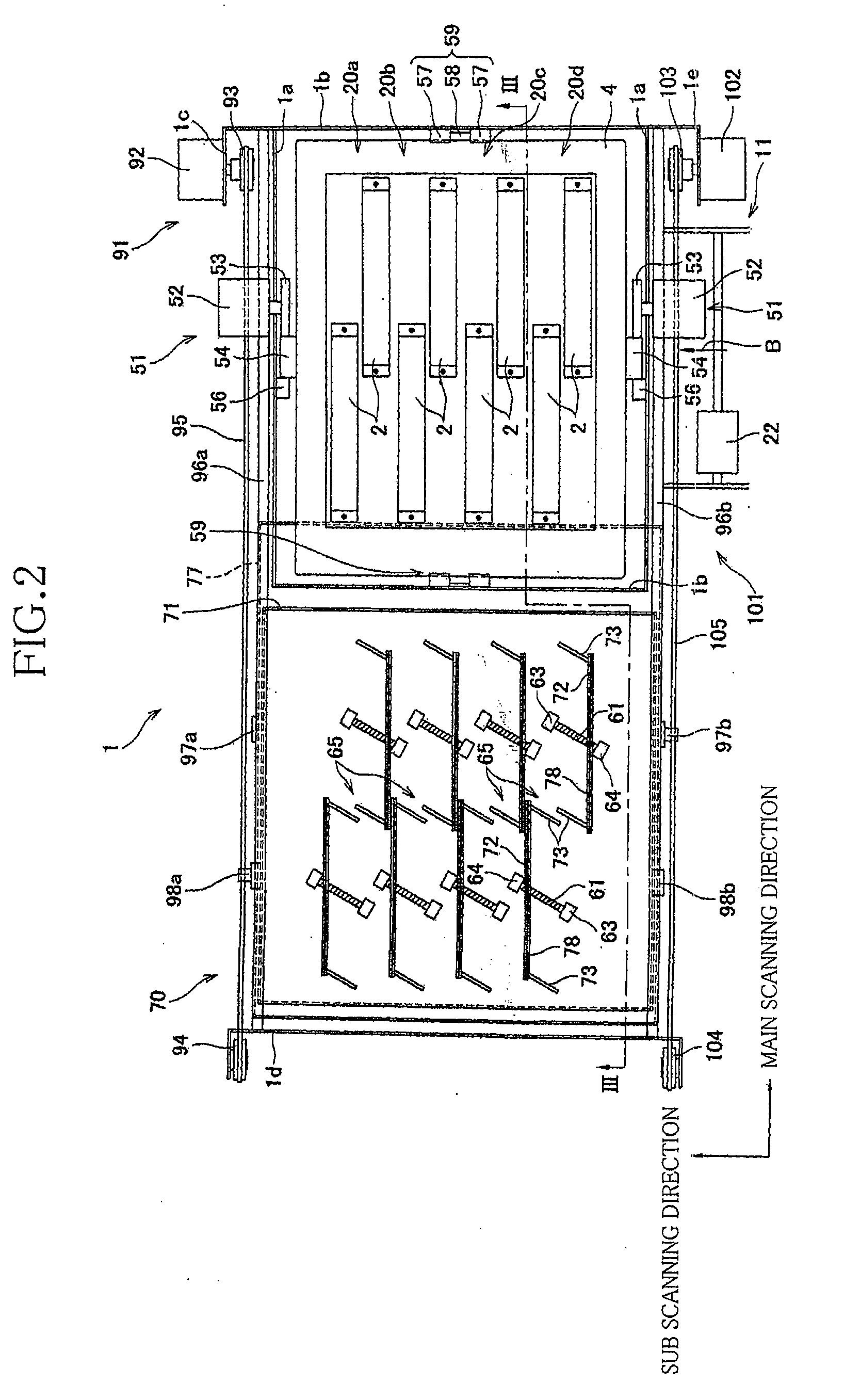
[0018]Referring first to FIG. 1, there will be explained an overall structure of the ink-jet printer according to the present embodiment. The ink-jet printer generally indicated at 1 in FIG. 1 is a color ink-jet printer of a line type that includes four head pairs 20a, 20b, 20c, 20d, each pair including two ink-jet heads 2 (each as a liquid ejecting head). The ink-jet printer 1 includes a sheet feeding mechanism 11 disposed on its left side as seen in FIG. 1 and a sheet discharging portion 12 disposed on its right side.

[0019]Inside the ink-jet printer 1, there is formed a sheet conveying path through which the recording sheet is conveyed from the sheet feeding mechanism 11 t...


PUM


Abstract

A liquid ejecting apparatus, including: a medium conveying mechanism which conveys a medium in a first direction; a head pair composed of two liquid ejecting heads respectively having liquid ejection surfaces in which liquid ejection areas are respectively formed, the two heads having respective one end portions overlapping each other as viewed in the first direction, and disposed such that the respective one end portions are adjacent to each other in the first direction; two wipers for wiping the respective ejection surfaces; and a wiper moving mechanism configured to move the two wipers in mutually opposite directions, wherein the ejection areas partly overlap each other as viewed in the first direction, wherein, when each wiper is placed by the wiper moving mechanism at a wiping start position at which each wiper does not face the corresponding ejection surface, the two wipers partly overlap each other as viewed in the first direction, and wherein, when each wiper is placed at a wiping complete position at which each wiper does not face the corresponding ejection surface, the two wipers overlap each other as viewed in a second direction perpendicular to the first direction.

Description

CROSS REFERENCE TO RELATED APPLICATION[0001]The present application claims priority from Japanese Patent Application No. 2008-012114 which was filed on Jan. 23, 2008, the disclosure of which is herein incorporated by reference to its entirety.BACKGROUND OF THE INVENTION[0002]1. Field of the Invention[0003]The present invention relates in general to a liquid ejecting apparatus including liquid ejecting heads which eject a liquid.[0004]2. Description of Related Art[0005]A known liquid droplet ejecting apparatus has a plurality of wiper blades for wiping nozzle surfaces of a plurality of heads arranged in a zigzag fashion. Each of the wiper blades in the above-indicated liquid droplet ejecting apparatus is disposed at widthwise one end of a corresponding one of the heads so as to extend over a dimension of the head as measured in its longitudinal direction, namely, extends over a longitudinal dimension of the head. The wiper blade is configured to move in a direction perpendicular to t...

Claims


Application Information

Patent Timeline
IPC IPC(8): B41J2/165
CPCB41J2/16585
Inventor TAMAKI, SHUICHICHIKAMOTO, TADANOBUSHINODA, AKIRAITO, NORITSUGU
Owner BROTHER KOGYO KK
Why Eureka
Try Eureka