LED light device having heat dissipating structure

Inactive Publication Date: 2009-07-23
CHEN CHIA YI
View PDF3 Cites 54 Cited by
  • Summary
  • Abstract
  • Description
  • Claims
  • Application Information

AI Technical Summary

Benefits of technology

[0009]The primary objective of the present invention is to provide an LED light device including a heat dissipating structure for dissipating the heat generated by the

Problems solved by technology

However, the heat generated by the high intensity discharge lamp may not be suitably dissipated and the accumulated heat may damage the high intensity discharge lamp.
Similarly, the other light members, such as the light bulbs, the light

Method used


Image

  • LED light device having heat dissipating structure
  • LED light device having heat dissipating structure
  • LED light device having heat dissipating structure

Examples


Example

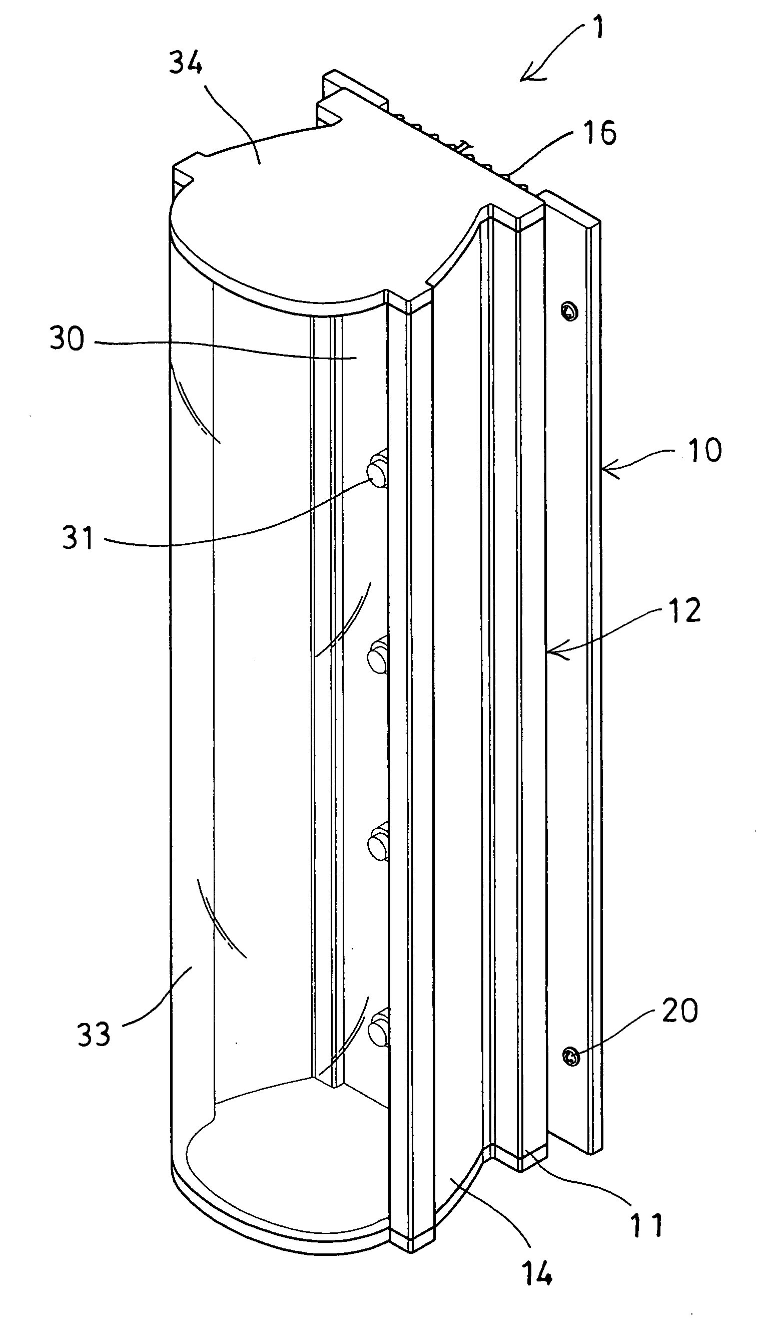
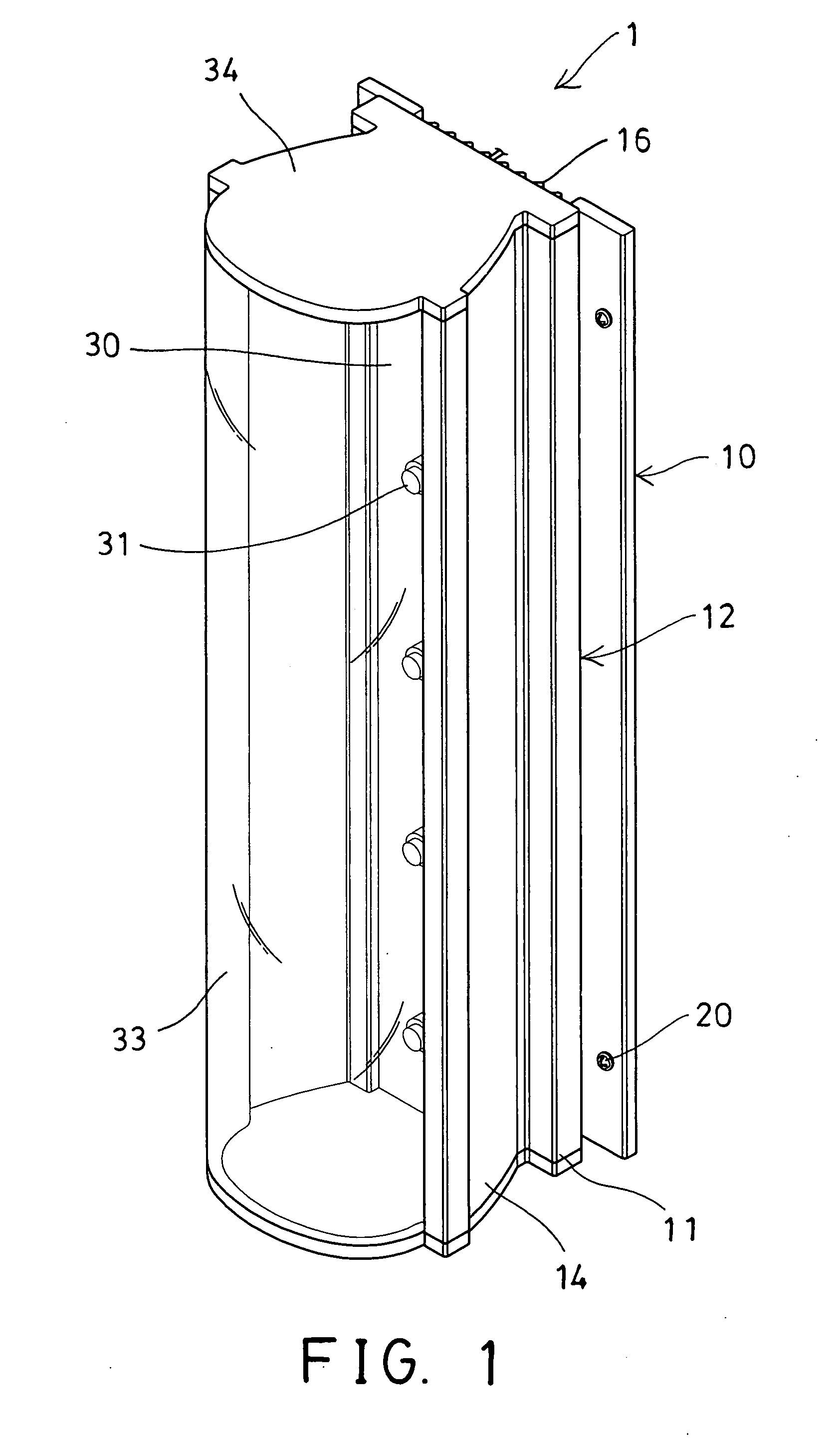
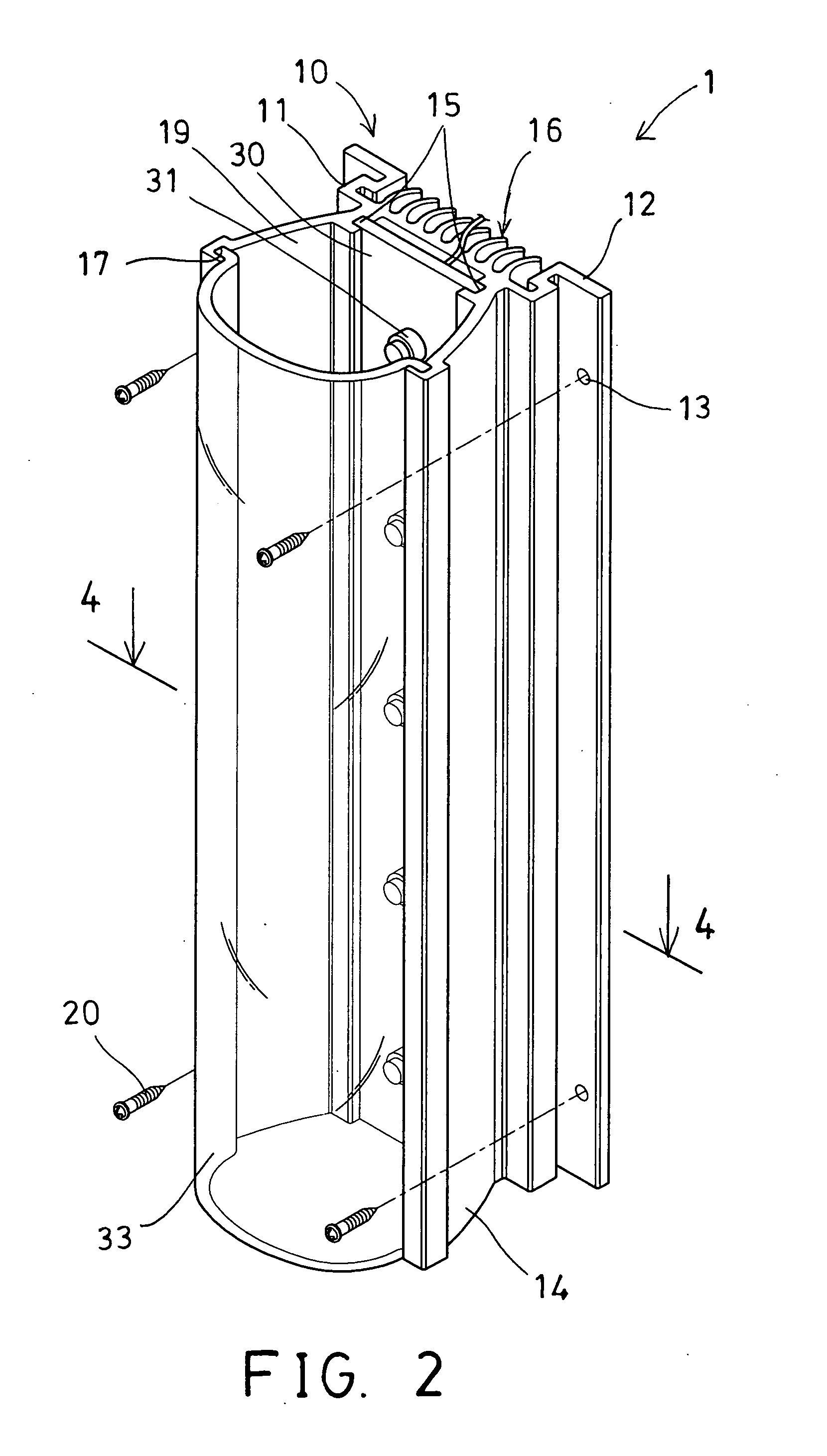
[0021]Referring to the drawings, and initially to FIGS. 1-4, an LED light device 1 in accordance with the present invention comprises a carrier or housing 10 including a base plate 11, and including one or more (such as two) brackets 12 attached to or extended from the side portions of the base plate 11 and / or extended rearwardly from the side portions of the base plate 11 and each having one or more orifices 13 formed therein for engaging with fasteners 20 which may secure the base plate 11 of the housing 10 to the ceiling structure or other supporting surfaces, and including two side walls 14 extended forwardly and outwardly therefrom and extended slightly away from each other for forming a chamber 19 between the side walls 14 and the base plate 11 and for light concentrating or condensing purposes.

[0022]The housing 10 further includes a channel 15 formed in the root portion of the side walls 14 and located close to the base plate 11 for slidably or detachably receiving or engagin...


PUM


Abstract

An LED light device includes a housing having a base plate, and two side walls extended forwardly and outwardly from the base plate for forming a chamber between the side walls and the base plate, one or more light elements disposed in the chamber of the housing for generating a light, and the housing includes a number of fins extended rearwardly from the base plate for dissipating a heat generated by the light element and for preventing the LED light device from being damaged by the heat and for increasing the brightness and the working life of the LED light device.

Description

BACKGROUND OF THE INVENTION[0001]1. Field of the Invention[0002]The present invention relates to a light emitting diode (LED) light device, and more particularly to an LED light device including a heat dissipating structure for dissipating the heat generated by the LED light device and for preventing the LED light device from being damaged by the heat and for increasing the brightness and the working life of the LED light device.[0003]2. Description of the Prior Art[0004]Typical light devices comprise a high intensity discharge lamp for generating the light, and a cylindrical transparent sleeve disposed around the high intensity discharge lamp for shielding the high intensity discharge lamp, and two end plates healingly attached to opposing ends of the cylindrical transparent sleeve for supporting the cylindrical transparent sleeve from a ceiling structure.[0005]For example, U.S. Pat. No. 6,247,830 to Winnett et al. discloses one of the typical heat shields for the agricultural ligh...

Claims


Application Information

Patent Timeline
IPC IPC(8): F21V29/00
CPCF21V3/00F21V15/013F21V17/104F21V29/74F21V29/004F21Y2101/02F21Y2103/003F21V19/0045F21Y2103/10F21Y2115/10
Inventor CHEN, CHIA-YI
Owner CHEN CHIA YI
Why Eureka
Try Eureka