

Apparatus and method for transmitting data using transmit antenna diversity in a packet service communication system
a packet service and antenna diversity technology, applied in the field can solve the problems of degrading the entire mobile communication system performance, affecting the transmission speed of packet service communication system, so as to achieve the effect of maximizing the transmission capacity of the packet service communication system
- Summary
- Abstract
- Description
- Claims
- Application Information
AI Technical Summary
Benefits of technology
Problems solved by technology
Method used
Image


Examples
embodiment 1
[0047]In accordance with the first embodiment of the present invention, a Node B selects orthogonal weights corresponding to maximum CQIs from feedback information received from a plurality of UEs and transmits data to UEs having the selected weights.
[0048]FIG. 3 is a flowchart illustrating the operation of the Node B and FIG. 4 is a block diagram of the Node B according to the first embodiment of the present invention.
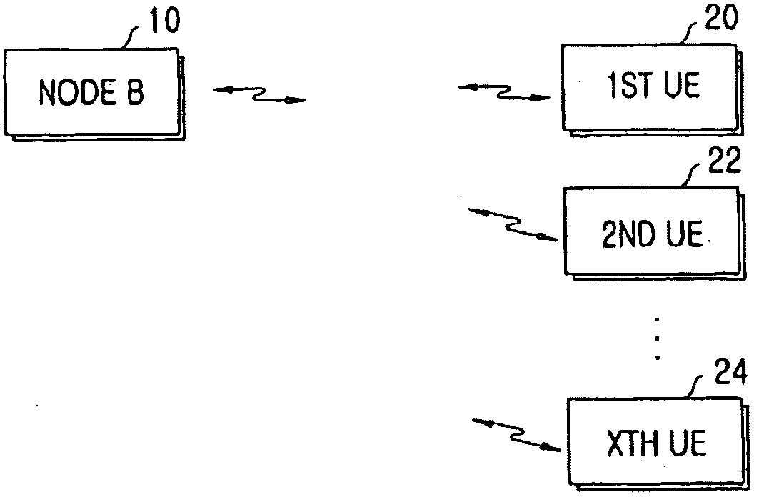
[0049]Referring to FIG. 4, the Node B 10 illustrated in FIG. 1 is comprised of AMC units 100 and 102 for applying AMC, gain multipliers 104 and 106; spreaders 108 and 110, weight multipliers 112, 114, 116 and 118, pilot summers 120 and 122, antennas 124 and 126, a feedback information interpreter 128, and a weight generator 130. The antennas 124 and 126 receive feedback information from the first to Xth UEs 20 to 24 on DPCCHs and transmit spatially processed HS-DSCH signals and CPICH signals to the UEs 20 to 24.
[0050]Referring to FIG. 3, the feedback information inter...
embodiment 2
[0061]In accordance with the second embodiment of the present invention, the Node B transmits packet data using quasi-orthogonal scrambling codes in the case where orthogonal weights corresponding to maximum CQIs selected from feedback information received from a plurality of UEs are not fully orthogonal.
[0062]FIG. 7 is a flowchart illustrating the operation of the Node B and FIG. 8 is a block diagram of the Node B according to the second embodiment of the present invention.
[0063]The Node B 10 illustrated in FIG. 8 is identical to the Node B 10 depicted in FIG. 4 in configuration. The Node 10 according to the second embodiment of the present invention is comprised of AMC units 220 and 222, gain multipliers 224 and 226, spreaders 228 and 230, weight multipliers 232, 234, 236 and 238, pilot summers 240 and 242, antennas 244 and 246, a feedback information interpreter 248, and a weight generator 250.
[0064]The feedback information interpreter 248 interprets weight & CQI information from...
PUM
 Abstract
Description
Claims
Application Information