
Transmitting and receiving device for a multipoint-to-point network

a multi-point-to-point network and transmission and receiving technology, applied in radio transmission, electrical equipment, synchronisation signal speed/phase control, etc., can solve the problems of insufficient utilization of existing transmission capacity and inability to provide information transmission, so as to improve utilization of existing transmission capacity and minimize the influence of information transmission

Inactive Publication Date: 2006-12-26
ALCATEL LUCENT SAS
View PDF11 Cites 1 Cited by
  • Summary
  • Abstract
  • Description
  • Claims
  • Application Information

AI Technical Summary

Benefits of technology

[0005]The object of the invention is therefore to provide a synchronization procedure which minimizes the influence on information transmission and thereby better utilizes the existing transmission capacity.
[0008]The transmission capacity for the communications signals is maximized by this procedure. Time gaps / areas no longer have to be kept free in the back channel for locking on; the communications signals can be emitted continuously. The lock-on time is also reduced due to the fact that firstly, a time gap / area no longer has to be awaited in which transmission of the synchronization signals has to take place, but on the contrary synchronization signals can now be emitted at any time.
[0009]Secondly, the hardware outlay for detecting the synchronization signals can be reduced due to the use of a special synchronization code, which is considerably shorter than the CDMA communications code.
[0010]The negative influence of the synchronization signals on the information signals can be minimized by control of the signal level, e.g. online, taking account of the actual signal-to-noise ratios.

Problems solved by technology

The second area is thus not available for information transmission, due to which the existing transmission capacity is not optimally utilized.

Method used


Image

  • Transmitting and receiving device for a multipoint-to-point network
  • Transmitting and receiving device for a multipoint-to-point network
  • Transmitting and receiving device for a multipoint-to-point network

Examples


Embodiment Construction

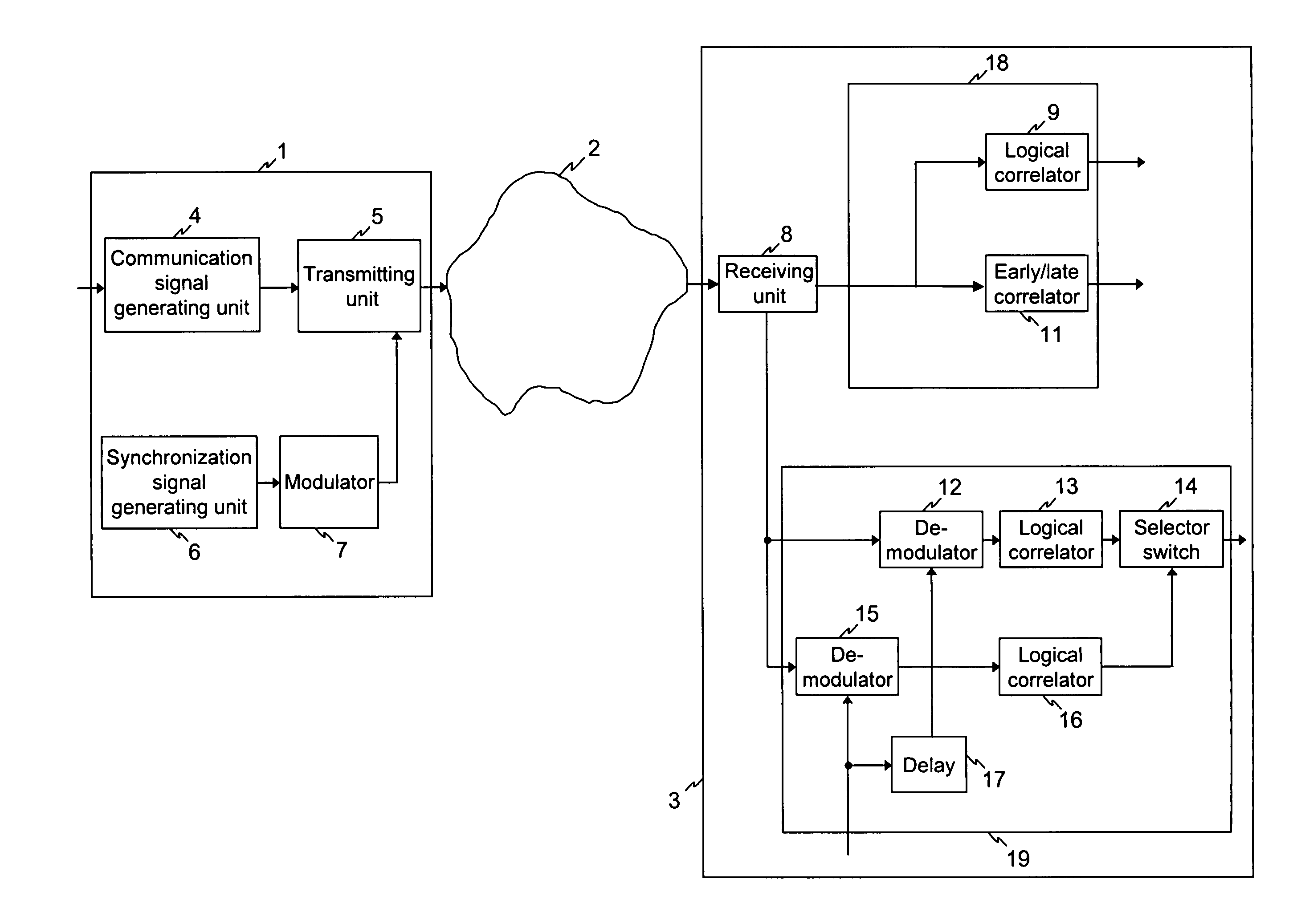
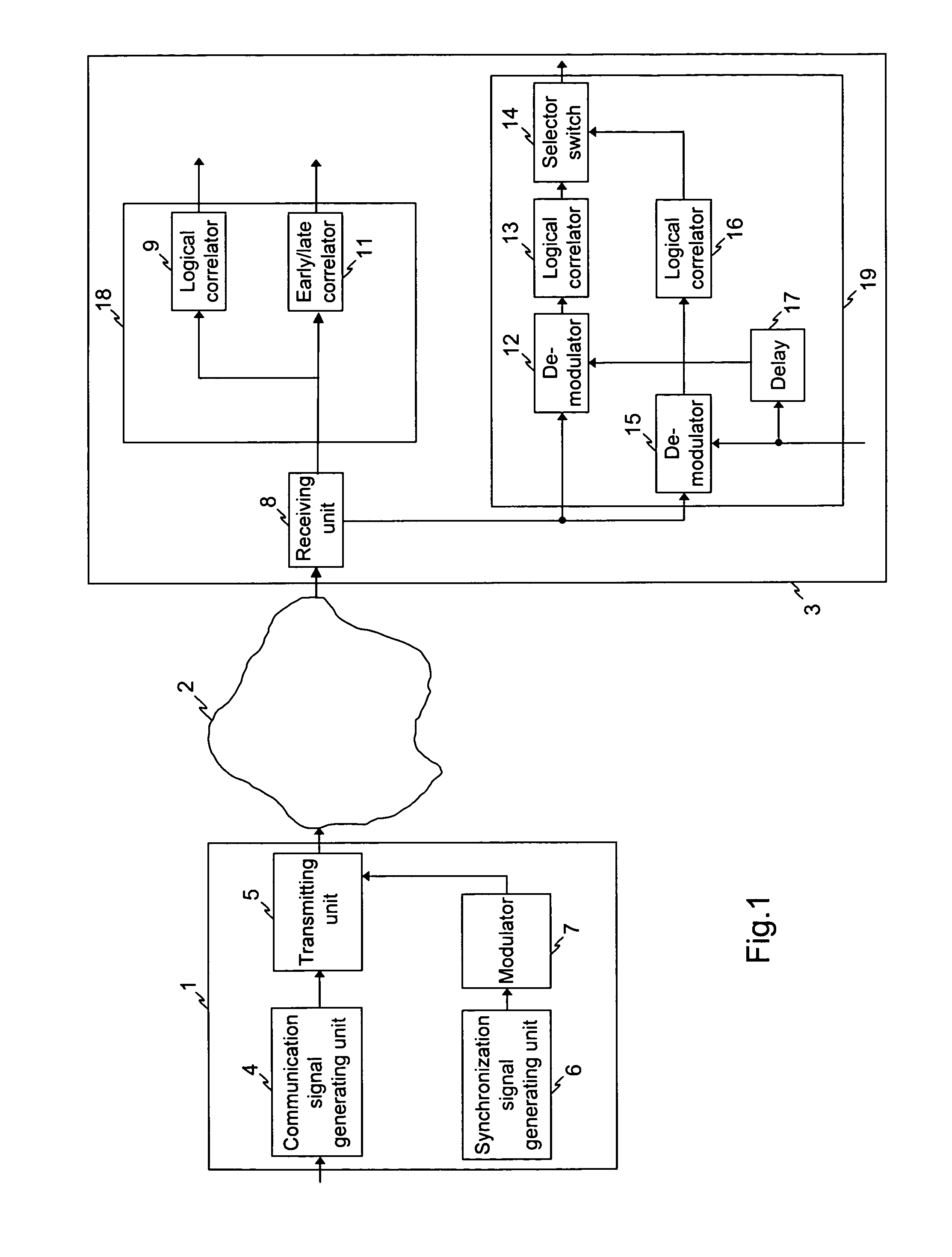
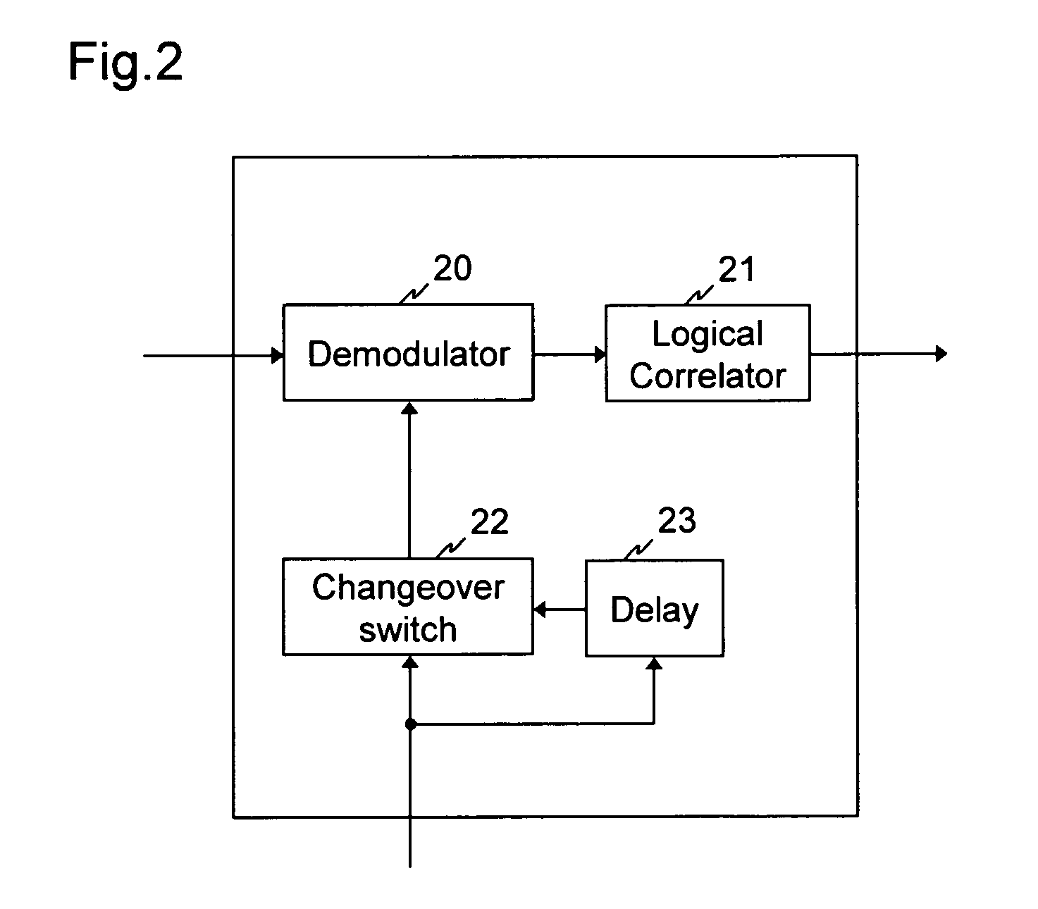
[0016]The first practical example is now explained with the aid of FIG. 1. FIG. 1 shows a CDMA multipoint-to-point network 2 with a transmitting device 1 according to the invention and a receiving device 3 according to the invention. The CDMA multipoint-to-point network 2 represents that part of an interactive communications network which is provided for implementing the back channel. For the forward channel of the interactive communications network, which is provided for the transmission of broadband information, such as television signals, video signals, control signals, from an exchange to several terminal stations, no diagrammatical representation is shown for reasons of clarity. The forward channel can be implemented for example by a hybrid network, which starting out from the exchange links the terminal stations to one another via a distribution network of optical glass fibre cables and optical splitters to form a point-to-multipoint network. Instead of optical cables, electri...


PUM


Abstract

A synchronization procedure for a multipoint-to-point CDMA network (2), which minimizes the influence on the information transmission. Instead of interleaving communications and synchronization signals timewise, a simultaneous emission is proposed, in which the synchronization signals are superimposed on the communications signals. The synchronization signals are coded with a special synchronization code (6), which does not correspond to the CDMA communications code of the information signals, e.g Barker code. In addition, the synchronization signals are sent at a lower amplitude compared with the communications signals. The synchronization signals are also modulated (7) prior to sending, in particular using alternating multiplication by +1 and −1. On the receiving side (3), the synchronization signals are detected by demodulation (12; 15), correlation (13; 16) and subsequent accumulation. The transmission capacity for the communications signals is maximized by this procedure and the influence of the synchronization signals on the communications signals minimized.

Description

BACKGROUND OF THE INVENTION[0001]The invention relates to a transmitting and a receiving device for a multipoint-to-point network, in particular a synchronous multipoint-to-point CDMA network, according to the preamble of claim 1 or the preamble of claim 3 and to a synchronization procedure for a multipoint-to-point network according to the preamble of claim 10.[0002]Multipoint-to-point networks, in particular multipoint-to-point CDMA networks, can be used advantageously to implement back channels in interactive communications networks. Interactive communications networks are executed for example as so-called HFC networks or HFR networks; HFC=Hybrid Fibre Coax, HFR=Hybrid Fibre Radio. For the forward channel, a point-to-multipoint network is used, which contains an optical feeder line plus a coaxial cable network or radio network connecting thereto. For the back channel, use is being made increasingly of a multipoint-to-point network, e.g. a CDMA network, which can be formed optical...

Claims


Application Information

Patent Timeline
IPC IPC(8): H04B7/216H04B1/707H04B7/26H04J7/00H04J13/00H04L7/06
CPCH04B1/708H04J7/00H04J13/00H04L7/06H04B1/7075H04B1/709H04B2201/70701H04B2201/709709
Inventor OTTERBACH, JURGENHALBAUER, HARDYSCHWOERER, GABRIELEJAENECKE, PETER
Owner ALCATEL LUCENT SAS
Learn More