Temperature measurement device

a temperature measurement and temperature technology, applied in the direction of sensors, material thermal analysis, diagnostics, etc., can solve the problems of less accuracy for shortened measurement time, inconvenient patient long measurement time, trade-off, etc., and achieve the effect of facilitating two or more measurement spots and different thermal boundary conditions

Inactive Publication Date: 2009-07-23
MEDISIM
View PDF8 Cites 19 Cited by
  • Summary
  • Abstract
  • Description
  • Claims
  • Application Information

AI Technical Summary

Benefits of technology

[0025]Furthermore, in accordance with another preferred embodiment of the present invention, the measurement locations are characterized as having distinct properties selected from the group of properties comprising: different thermal conductivity, different thickness, or different emissivity, thus facilitating different boundary conditions on the external surface.
[0026]Furthermore, in accordance with another preferred embodiment of the present invention, the patch comprises at least one of a plurality of measurement locations characterized in that each measurement location facilitates two or more measurement spots facilitating different thermal boundary conditions on the external surface.

Problems solved by technology

Such a long measurement time is inconvenient for the patient.
However, often this incurs a tradeoff of less accuracy for shortened measurement time.
However, such a measurement is considered invasive, which may disturb the patient.
Also, there is a limitation due to the fact that ear canal is not always straight so there is no direct line of sight to the eardrum.
Furthermore, when using radiation for direct skin temperature measurement, the measurement is affected by environment temperature.
However, having the thermometer attached to the body is problematic.
It is inconvenient for the patient to “carry” such a device for a long time, especially for babies.

Method used


Image

  • Temperature measurement device
  • Temperature measurement device
  • Temperature measurement device

Examples


second embodiment

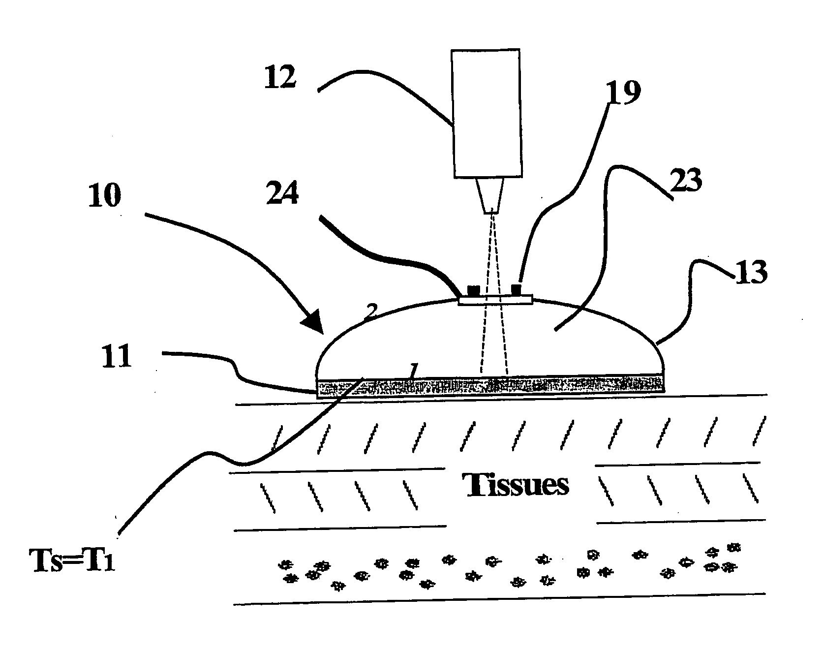
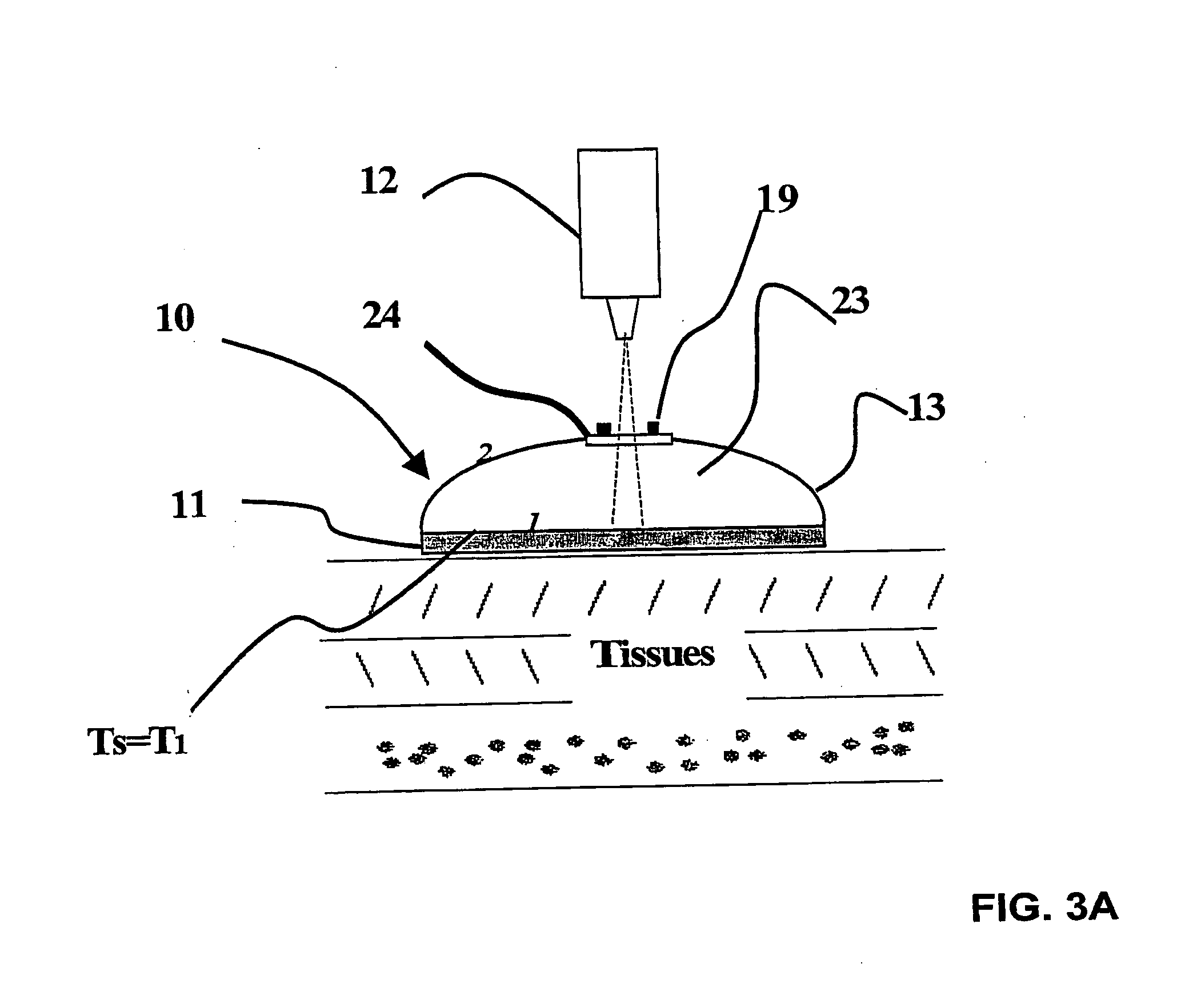
[0111]One implementation of reader 12 is as an IR radiometer that reads the IR radiation at the points (FIG. 3A). In that case, it is necessary for cover 13, which is opaque to radiation, to include an aligner 19 for aligning reader 12 over the point and a small access point 24 in cover 13 through which radiation can pass for reading by the radiometer. One way to implement access point 24 is to make it permanently IR-transparent but small enough not to allow significant IR radiation to escape, for example as a window or opening. Another way to implement access point 24 is to make it IR-opaque but capable of being opened by radiometer reader 12 at the time of the reading, for example, as a spring-hinged shutter that is pushed open by the radiometer and closes when the radiometer is removed or as a diaphragm such as an aperture used to light entering a camera. Although it is not critical in this embodiment and in the second embodiment, how much radiation escapes through access point 2...

first embodiment

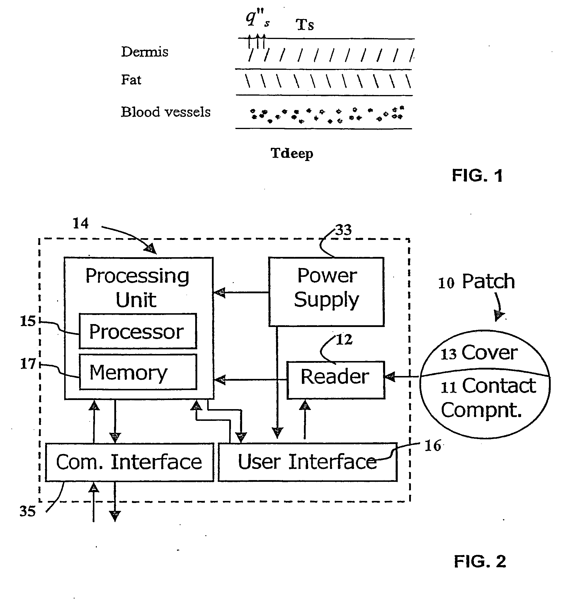
[0122]the present invention is now described with reference to FIG. 3A. This embodiment requires that reader 12 be the IR radiometer implementation described earlier with reference to FIG. 3A. Therefore, in this embodiment, cover 13 of patch 10 comprises access point 24, enabling IR-radiation reading. Two readings are made, one measurement through access point 24 of IR radiation at a point, such as the one labeled 1 in the figure, on the surface of contact component 11, the other one, such as the one labeled 2 in the figure, on the external surface of cover 13. As will be explained later, for greatest accuracy, it is preferably to measure at least three pairs of such points 1 and 2, for example using a patch 10 implementation such as the one shown in FIG. 5A. In that implementation, contact component 11 is divided into three sections, A, B, and C, each having a different thermal boundary condition, hence a different q″s and Ts. Thermal boundary conditions of points on contact compon...

third embodiment

[0192]the present invention is now described with reference to FIG. 9, which is a cross section side view of patch 10. In this configuration we assume that qs″≈0 and no radiation or convection effects occur on the surface. In this case, if the contact component 11 is big enough to avoid lateral heat flux and the cover 13 emissivity is low on both its internal and external surface (for example with a reflective surface) and if access element 24 does not leak a significant amount of radiation (for example a small opening having an area of less than 5% of the total area of the cover), then we can assume that Ts is close enough to Tdeep to be considered equivalent. Therefore, a direct measurement of Ts can be used to find Tdeep. For example, in the case of human body temperature measurement, a patch could have a with diameter larger than 20 mm and a cover 13 having emissivity of less than 0.1 on both surfaces of the cover being.

[0193]In order to get good signal to noise ratio, one can u...


PUM


Abstract

A device for non-invasive measurement of the internal temperature of a physical body or thermal resistivity, the body comprising a thermally conductive medium between an internal region with a substantially constant internal temperature and an external surface with a surface temperature. The device comprises: a patch comprising one or more contact components for attachment to the external surface and an insulating cover for substantially thermally insulating the contact component from ambient thermal conditions; a reader for acquiring one or more thermal magnitudes on the patch; a processing unit for processing the thermal magnitudes to derive the internal temperature of the internal region or the thermal resistivity of the conductive medium.

Description

CROSS-REFERENCE TO RELATED APPLICATION[0001]This application is a continuation of U.S. patent application Ser. No. 11 / 597,246, filed Sep. 10, 2007.FIELD OF THE INVENTION[0002]The present invention relates to high speed, accurate temperature measurement. More particularly it relates to a device for calculating an object's internal temperature based on measuring the object's surface temperature.BACKGROUND OF THE INVENTION[0003]Internal temperature of a physical object can be determined from the object's external surface temperature as measured using conduction-based devices or radiation-based devices. The object being measured is assumed to have an interior with an internal temperature in a substantially steady state and external surface. There are many examples where it is desirable to know the internal temperature of such an object Examples: monitoring the safety level inside a tank holding hazardous chemicals, determining whether livestock are ready for insemination, or checking th...

Claims


Application Information

Patent Timeline
Patent Type & Authority Applications(United States)
IPC IPC(8): A61B5/01
CPCA61B5/01G01J5/0022G01J5/0025G01K13/002G01J5/0887G01K1/165G01K7/42G01J5/08G01K13/20
Inventor YARDEN, MOSHEBARAK, MENASHE
Owner MEDISIM
Why Eureka
Try Eureka