Motion Control Device for Vehicle

a technology of motion control and vehicle, which is applied in the direction of braking system, instruments, analogue processes for specific applications, etc., can solve the problems of vehicle not being able to accelerate, driver discomfort, and driver discomfor

Active Publication Date: 2009-07-23
ADVICS CO LTD +1
View PDF4 Cites 71 Cited by
  • Summary
  • Abstract
  • Description
  • Claims
  • Application Information

AI Technical Summary

Problems solved by technology

Further, the uncomfortable feeling of the driver occurs when the vehicle is decelerated by the control even though the driver attempts to accelerate the vehicle, the vehicle cannot be accelerated because of the control even though the driver desires to accelerate, and the like.
Thus, in a case where the speed reduction control is not finished until the vehicle passes over the curve ending point as disclosed in JP2005-170152A, the uncomfortable feeling of the driver may remain.
First, in a case where the deceleration operation is performed by the driver, the speed reduction control is required to assist the driver's deceleration operation by decelerating the vehicle to the appropriate vehicle speed.
That is, the aforementioned two types of speed reduction control are not assumed or considered and therefore are not selectable depending on the operation condition of the vehicle.

Method used


Image

  • Motion Control Device for Vehicle
  • Motion Control Device for Vehicle
  • Motion Control Device for Vehicle

Examples


first embodiment

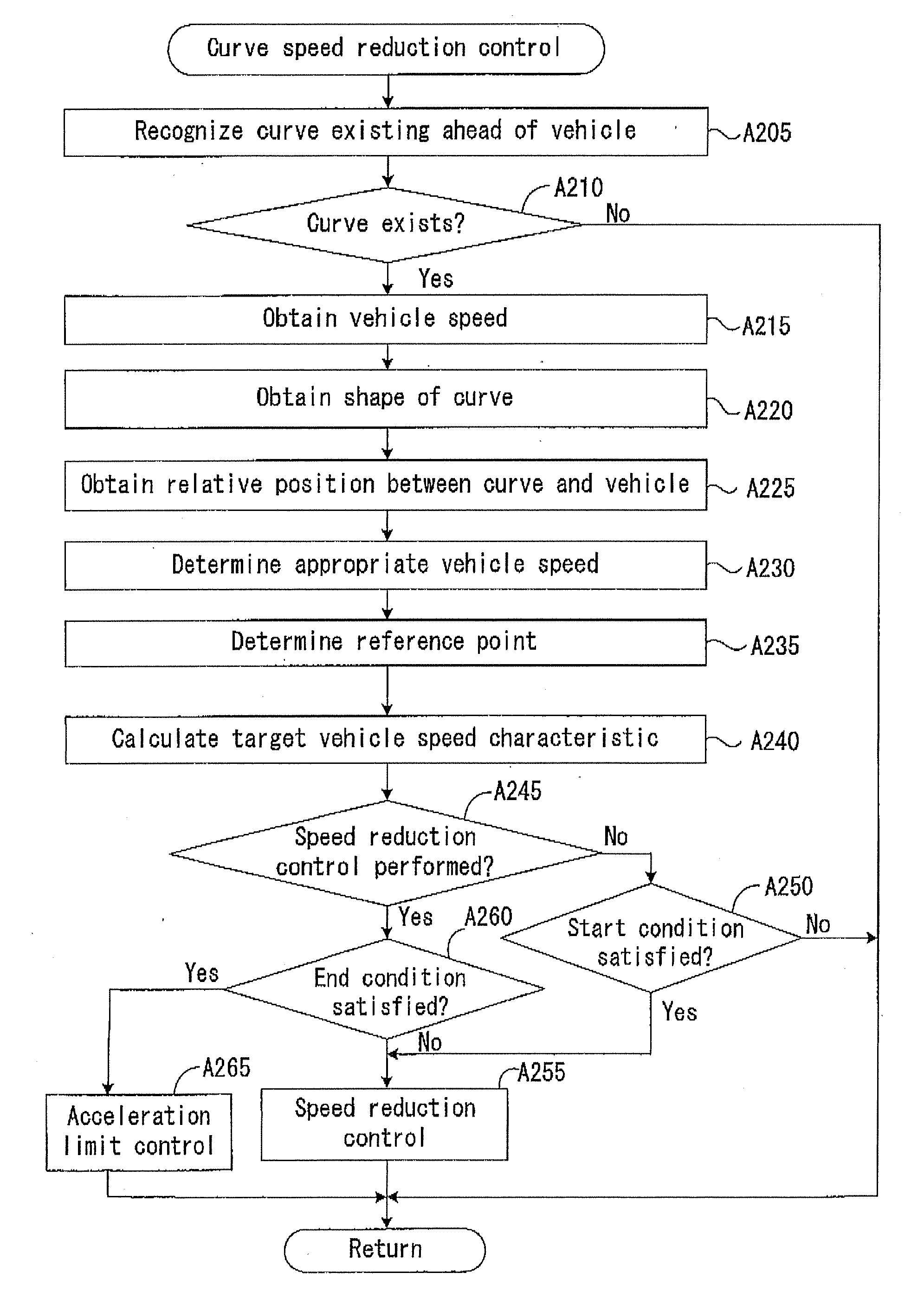
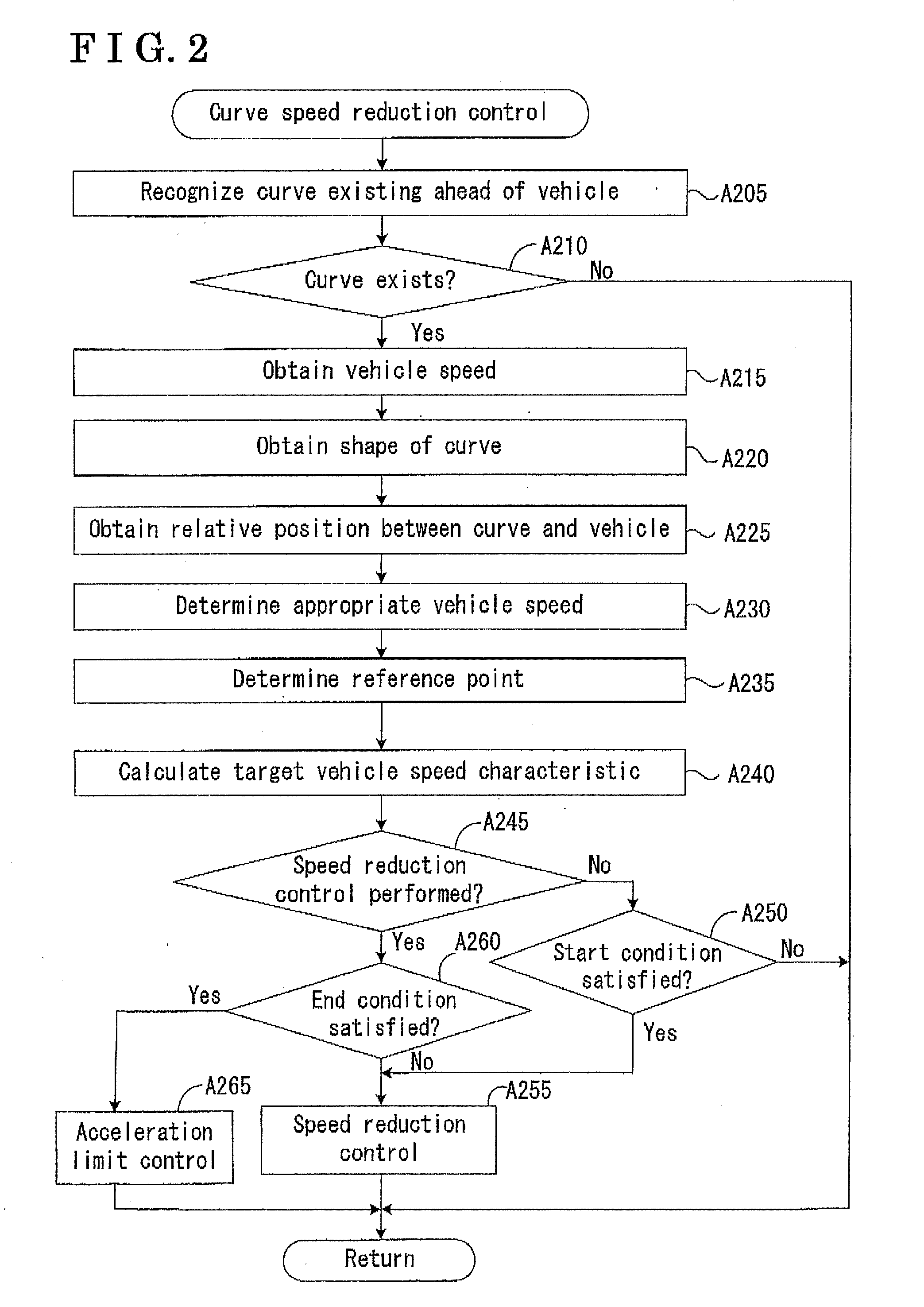
[0109]According to the motion control device of the first embodiment, the curve speed reduction control is performed, regardless of the acceleration / deceleration operation by the driver, for the purpose of decreasing the vehicle speed Vx to the appropriate vehicle speed Vq that is achieved at the reference point Pcr (which is equal to, for example, the advance transition curve zone ending point or the closer point to the vehicle relative to the advance transition curve zone ending point) provided in the middle of the curve. The vehicle is therefore appropriately driven through the curve. That is, the curve speed reduction control is performed regardless of whether or not the vehicle advances to the curve.

[0110]In addition, when the vehicle is decelerated to the appropriate vehicle speed Vq, the curve speed reduction control is finished regardless of whether or not the vehicle exits from the curve. Accordingly, the curve speed reduction control (specifically, the start timing and the...

second embodiment

[0185]FIG. 25 illustrates an example of a case where the first control (travel assistance control) is performed by the device according to the When the vehicle passes over the point Pcs1 at which the first control execution condition is satisfied, the first control is started. Accordingly, the limitation of the throttle opening degree (the throttle opening degree does not exceed an upper limit value although the throttle opening degree is allowed up to the upper limit value), the increase of the reduction gear ratio of the transmission TM (downshift from the shift stage Tr to the shift stage Ts), and the application of the brake torque (brake pressure) by the wheel brake are started.

[0186]In the example shown in FIG. 25, the brake torque (brake pressure) is not applied by the wheel brake. This is because of the following reasons. That is, the first deceleration Gx1 of the first control smaller than the second deceleration Gx2 of the second control is achievable only by the limitati...


PUM


Abstract

A motion control device for a vehicle includes a vehicle speed obtaining means for obtaining a speed of the vehicle, a curve shape obtaining means for obtaining a shape of a curve existing ahead of the vehicle on a road on which the vehicle is traveling, a position obtaining means for obtaining a relative position of the vehicle to the curve, a determining means for determining an appropriate vehicle speed for the vehicle to travel through the curve based on the shape of the curve obtained by the curve shape obtaining means, and a speed reduction controlling means for performing a speed reduction control on the vehicle based on the appropriate vehicle speed determined by the determining means.

Description

CROSS REFERENCE TO RELATED APPLICATIONS[0001]This application is based on and claims priority under 35 U.S.C. §119 to Japanese Patent Application No. 2008-012453, filed on Jan. 23, 2008 and No. 2008-014347, filed on Jan. 25, 2008, the entire contents of which are incorporated herein by reference.FIELD OF THE INVENTION[0002]This invention generally relates to a motion control device for a vehicle. More particularly, this invention pertains to a motion control device for a vehicle for executing an automatic reduction of a speed of the vehicle (i.e., a speed reduction control) when the vehicle travels through a curve existing ahead of the vehicle on a road on which the vehicle is traveling.BACKGROUND[0003]A known motion control device for a vehicle is disclosed in JP3385812B. According to the motion control device disclosed, in order to achieve an appropriate advancing vehicle speed when the vehicle advances to the curve, a deceleration distance required for the vehicle to be decelerat...

Claims


Application Information

Patent Timeline
Patent Type & Authority Applications(United States)
IPC IPC(8): G06F19/00B60W10/10B60W10/18B60W30/02
CPCB60W10/06B60W10/11B60W10/184B60W30/045B60W2550/402B60W40/076B60W2520/10B60W2550/143B60W40/072B60W30/18145B60W2552/20B60W2552/30B60W2556/50
Inventor YASUI, YOSHIYUKINAKANO, KEITAKODAMA, HIROYUKIMARUYAMA, MASAKIMIYAJIMA, TAKAYUKIKONDO, YOSHITOTAKEUCHI, ATSUSHI
Owner ADVICS CO LTD
Why Eureka
Try Eureka