Matrix Free Non-Woven Layer of Polypyridazle Short Fiber
a technology of polypyridazle and short fiber, applied in the field of non-woven layers, can solve problems such as compromising the effectiveness of armor against penetration
- Summary
- Abstract
- Description
- Claims
- Application Information
AI Technical Summary
Problems solved by technology
Method used
Image
Examples
example 1
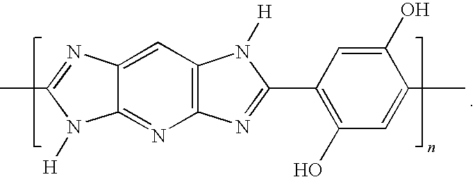
[0036]In the Example 1 of this invention, felt made of M5® fiber is prepared from the continuous filament yarns of M5® with a tenacity of 35 gpd, modulus of 2000 gpd, and fiber density of 1.65 g / cm3. The continuous filaments yarns were first crimped and then cut into about 5 cm length short staple fibers. The staple fibers were then converted into felt via a variety of equipment and process, including needle punching, well known to the trade. The areal density of the compacted layer of M5® felt is 180 g / m2. Twenty-one layers of the M5® felt of this invention with about 15″×15″ size are stitched together around the edge and with a cross stitch to form a composite structure with a total areal density of about 3.8 kg / m2. The assembly is then tested against 17-grain fragment per MIL-STD-662E testing standard. The result of V50 is expected to be better than that of the prior art with woven fabric, as described in Comparative Example 1.
example 2
[0037]In the Example 2 of this invention, felt made of M5® fiber is prepared from the continuous filament yarns of M5® having a tenacity of 35 gpd, modulus of 2000 gpd, and fiber density of 1.65 g / cm3. The continuous filaments yarns were first crimped and then cut into about 5 cm length short staple fibers. The staple fibers were then converted into felt via a variety of equipment and process, including needle punching, well known to the trade as described in Example, except that the areal density of the compacted layer of M5® felt is 420 g / m2. Nine layers of the M5® felt of this invention with about 15″×15″ size are stitched together around the edge and with a cross stitch to form a composite structure with a total areal density of about 3.8 kg / m2. The assembly is then tested against 17-grain fragment per MIL-STD-662E testing standard. The result of V50 is expected to be better than that of the prior art with woven fabric, as described in Comparative Example 1.
example 3
[0038]In the Example 3 of this invention, felt made of M5® fiber is prepared from the continuous filament yarns of M5® having a tenacity of 35 gpd, modulus of 2000 gpd, and fiber density of 1.65 g / cm3 as disclosed in Example 1. The short staple fibers were produced by stretch broken of the continuous filament yarns into a typical length of 7 and 11 cm. The staple fibers were then converted into felt via a variety of equipment and process, including needle punching, well known to the trade. The areal density of the compacted layer of M5® felt is 180 g / m2. Twenty-one layers of the M5® felt of this invention with about 15″×15″ size are stitched together around the edge and with a cross stitch to form a composite structure with a total areal density of about 3.8 kg / m2. The assembly is then tested against 17-grain fragment per MIL-STD-662E testing standard. The result of V50 is expected to be better than that of the prior art with woven fabric, as described in Comparative Example 1.
PUM
| Property | Measurement | Unit |
|---|---|---|
| Length | aaaaa | aaaaa |
| Length | aaaaa | aaaaa |
| Percent by mass | aaaaa | aaaaa |
Abstract
Description
Claims
Application Information
 - R&D
- Intellectual Property
- Life Sciences
- Materials
- Tech Scout
- Unparalleled Data Quality
- Higher Quality Content
- 60% Fewer Hallucinations
Browse by: Latest US Patents, China's latest patents, Technical Efficacy Thesaurus, Application Domain, Technology Topic, Popular Technical Reports.
© 2025 PatSnap. All rights reserved.Legal|Privacy policy|Modern Slavery Act Transparency Statement|Sitemap|About US| Contact US: help@patsnap.com

