Effusion cooling for gas turbine combustors

Inactive Publication Date: 2009-07-30
HONEYWELL INT INC
View PDF15 Cites 8 Cited by
  • Summary
  • Abstract
  • Description
  • Claims
  • Application Information

AI Technical Summary

Problems solved by technology

The hot combustion gases create a temperature environment that may limit the useful operating time, and ultimately, the component life of the combustor and other components of the engine.
Conventional systems and methods for cooling the combustor, such as louvers and impingement cooling, have been met with mixed success, at best.

Method used


Image

  • Effusion cooling for gas turbine combustors
  • Effusion cooling for gas turbine combustors
  • Effusion cooling for gas turbine combustors

Examples


Embodiment Construction

[0013]The following detailed description of the invention is merely exemplary in nature and is not intended to limit the invention or the application and uses of the invention. Furthermore, there is no intention to be bound by any theory presented in the preceding background of the invention or the following detailed description of the invention.

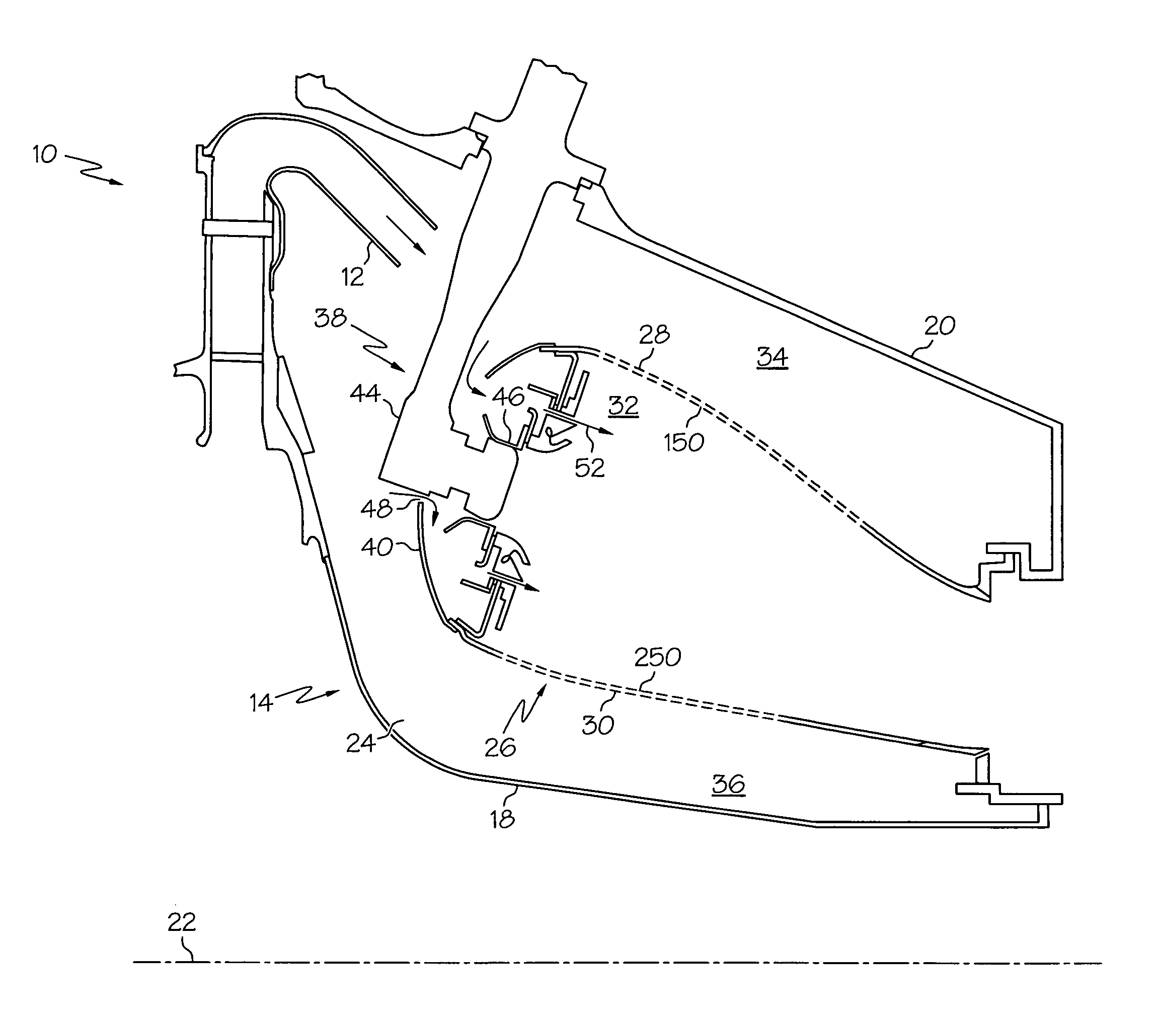
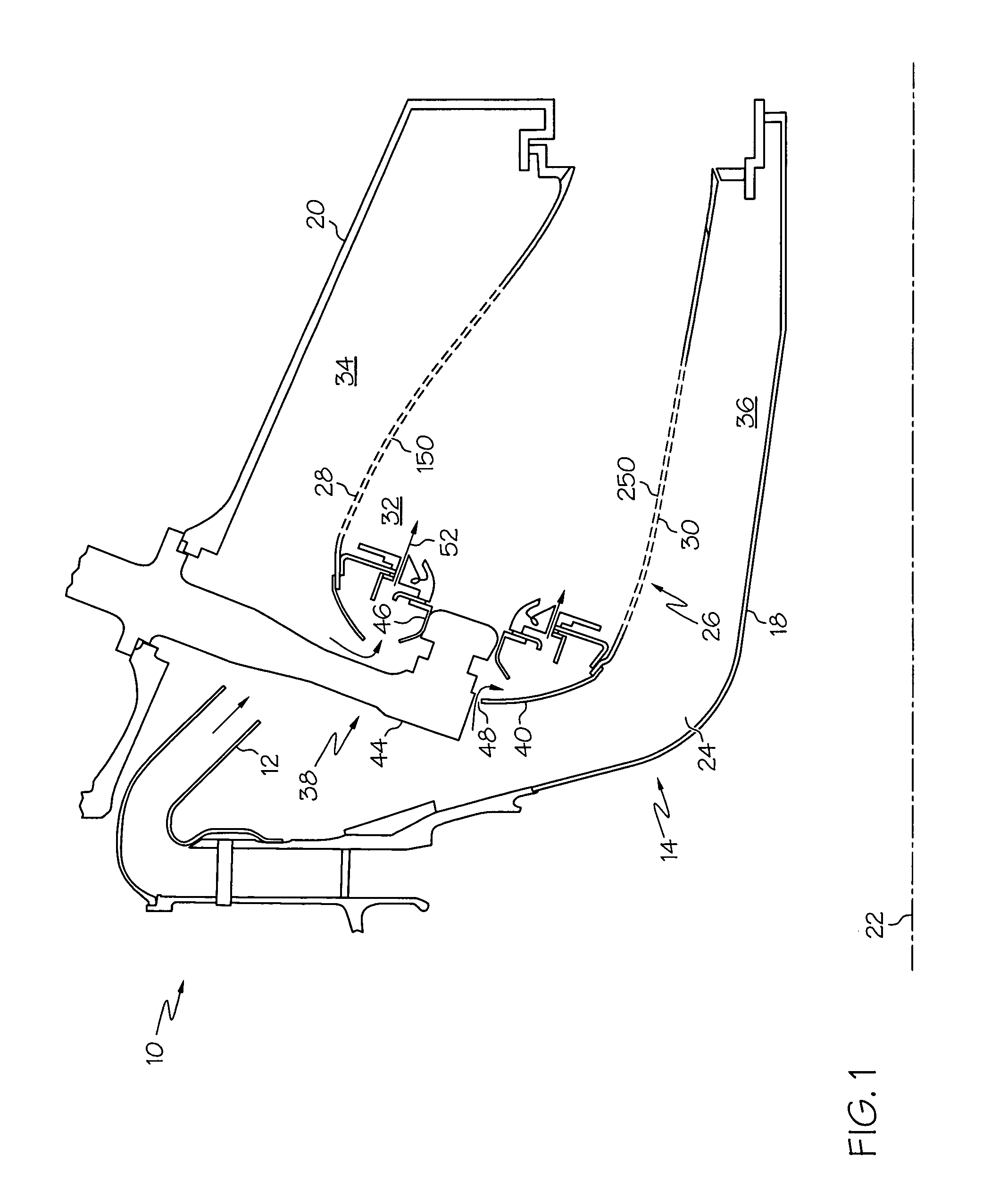
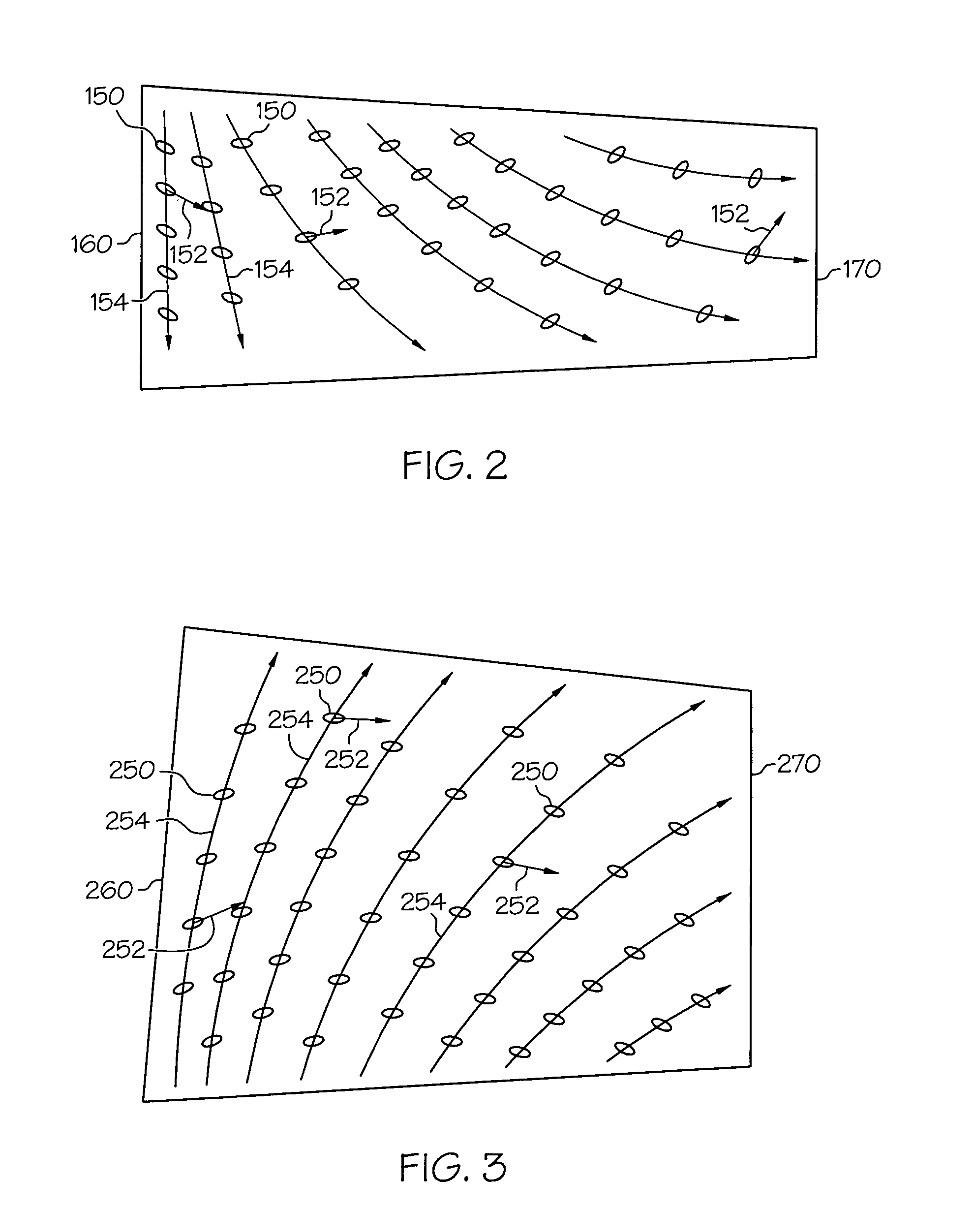
[0014]Broadly, the exemplary embodiments discussed herein provide cooling schemes for combustors of gas turbine engine assemblies. More particularly, the inner and outer liners of the combustors are provided with effusion cooling holes for supplying a film of cooling air to inner surfaces. The effusion cooling holes can be oriented as a function of the streamlines of the combustion gases. The effusion cooling holes can be used to cool the relatively large inner surface areas of the combustion chambers in an efficient manner. Embodiments discussed herein may find beneficial use in many industries and applications, including aerospace, automot...


PUM


Abstract

A combustor for a turbine engine includes an outer liner and an inner liner circumscribed by the outer liner to form a combustion chamber therewith in which an air and fuel mixture is combusted to form streamlines of combustion gases. A first plurality of effusion cooling holes is formed in at least one of the inner or outer liners, with the first plurality of effusion cooling holes being oriented as a function of the streamlines.

Description

STATEMENT REGARDING FEDERALLY SPONSORED RESEARCH OR DEVELOPMENT[0001]This invention was made with Government support under contract numbers DAAH10-98-C0023 and F33615-98-C-2803 awarded by the JTAGG III program of the US Government. The Government has certain rights in this invention.TECHNICAL FIELD[0002]The present invention generally relates to gas turbine engines, and more particularly, to schemes for cooling combustors of gas turbine engines.BACKGROUND[0003]Gas turbine engines, such as those used to power modern commercial aircraft, include a compressor for pressurizing a supply of air, a combustor for burning a fuel in the presence of the pressurized air, and a turbine for extracting energy from the resultant combustion gases. The combustor typically includes radially spaced apart inner and outer liners that form a combustion chamber in which the fuel and air mixture is burned.[0004]The hot combustion gases create a temperature environment that may limit the useful operating tim...

Claims


Application Information

Patent Timeline
IPC IPC(8): F02G3/00
CPCF23R3/002F23R3/06Y02T50/675F23R2900/03041F23R3/50Y02T50/60
Inventor WOODCOCK, GREGORY O.HANSON, AMY T.REYNOLDS, ROBERT S.ARMSTRONG, MIKE
Owner HONEYWELL INT INC
Why Eureka
Try Eureka