
Lock Device

a technology of locking device and locking mechanism, which is applied in the direction of wing knobs, roofs, keyhole guards, etc., can solve the problems of low resistance of locks to unauthorized unlocking actions, ineffective unauthorized action of operating buttons, and high probability of gap formation, so as to improve operating performance and quality, effectively and reliably transmit respective operating forces, and maintain stable operation. the effect of performan

Active Publication Date: 2009-07-30
NIFCO INC
View PDF7 Cites 10 Cited by
  • Summary
  • Abstract
  • Description
  • Claims
  • Application Information

AI Technical Summary

Benefits of technology

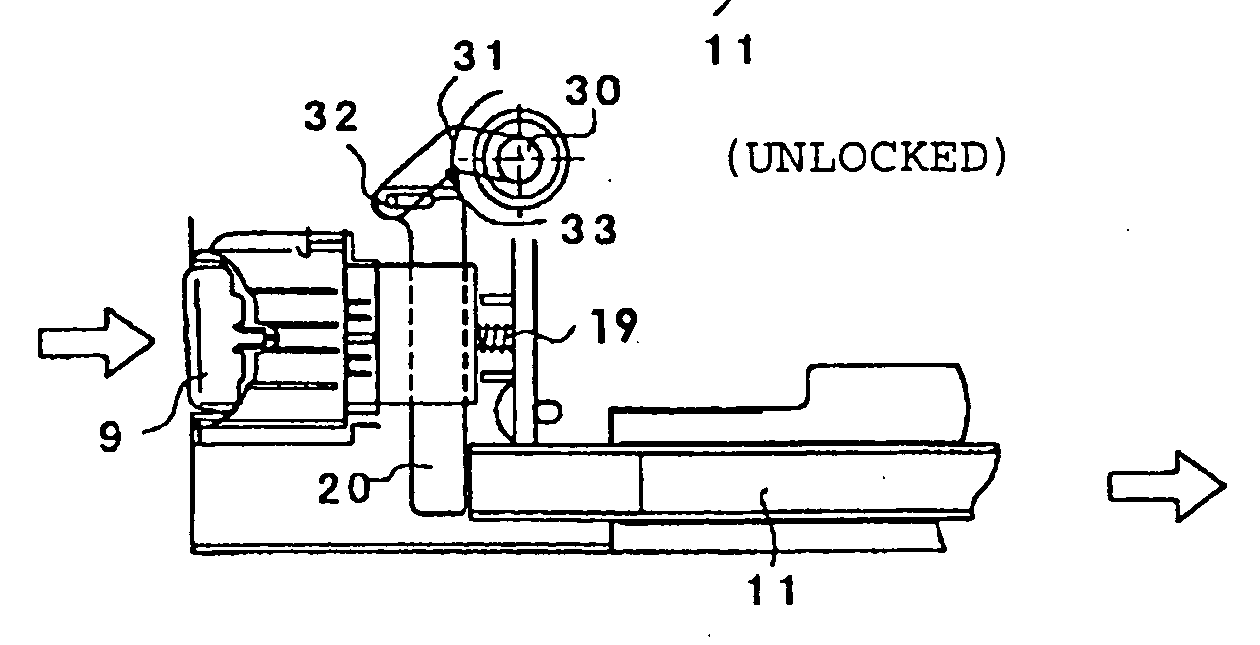
[0016]In accordance with the present invention, unauthorized actions applied to the operating button are made ineffective in the locked position, and the engagement member is configured to be slid through the coupling member to be brought out of engagement with the counterpart of the body and to switch the lid member from the closed state to an open state by operating the operating button only in the unlocked position. In other words, although the lock device according to the present invention is the same as the one disclosed in Patent Document 2 in that unauthorized actions applied to the operating button are made ineffective, the lock device according to the present invention is free of problems, such as an excessive load and local wear, in comparison with the one disclosed in Patent Document 2 to improve operating performance and quality for reasons, e.g. that the engagement member is configured to be slid without being turned, and that the engagement member is configured to be slid through the coupling member as a different member disposed between the operating button and the engagement member so as to bring the engageable portions out of engagement with the main body by operating the operating button in the unlocked position.
[0017]When the coupling member is supported so as to be slidable in a direction substantially orthogonal to the depressing direction of the operating button, and when the engagement member is supported so as to be slidable in substantially the same direction as the depressing direction of the operating button, it is possible to effectively and reliably transmit respective operating forces to respective parts to stably maintain the operating performance because of the characteristic allocation of the coupling member to the operating button and the characteristic allocation of the engagement member to the operating button. When the lock device includes a rotor rotated by each of the locking operation and the unlocking operation applied to the lock, and an arm disposed on the rotor so that the arm is operatively coupled to one end of the coupling member to slide the coupling member in synchronization with rotation of the rotor, it is possible to stably maintain operating performance since the coupling member is linearly slid to selectively couple the operating button to the engagement member and disconnect the operating button from the engagement member in response to the locking and unlocking operations (key operations) applied to the lock.
[0018]When the engagement member has the engageable portion disposed at least two positions in a sliding direction, it is not only difficult for a gap to be formed between the lid member and the main body even if the lid member has a great length but also possible to double the resistance to unauthorized unlocking actions, i.e. a force for keeping the lid engaged with the main body in the locked position. When the lock device further includes a biasing member for returning the operating button to the original position after the operating button is operated, and another biasing member for returning the engagement member in a direction to bring the engageable portion into engagement with the counter part of the main body, it is possible to set the engagement of the engageable portion with the main body, i.e. the holding force at a designed level since the operating button can be reliably returned to the original position after operation by being biased by its dedicated biasing member and since the engagement member is biased by its dedicated biasing member. When the main body is a console box, and when the lid member is swingably coupled to the console box at one end thereof in a longitudinal direction thereof and has the engagement member disposed along the other end in the longitudinal direction, there is provided a preferred lock device with a lock, which can solve all problems that has been caused since the console box itself has a great length in a front-to-rear direction and a large size as discussed in the introduction part.

Problems solved by technology

This leads to a situation where the lock has a low resistant against unauthorized unlocking actions, i.e. a low locking force in a locked position.
If the lid member has a great length or a large size, a gap is highly likely to be formed.
In the prior art disclosed in Patent Document 2, even if an attempt is made to operate an operating button in the locked position, any unauthorized action to the operating button is ineffective.
Although it is possible to eliminate a damage factor caused by forcibly operating the operating button, the resistance to unauthorized unlocking actions, i.e. the locking force in the locked position is low, which has caused the same problem as Patent Document 1.
Further, since the structure disclosed in the latter prior art is configured, e.g. so that the hook is swung to be selectively brought into engagement with and disengagement from a counterpart of the glove box, and that when the main box of the console box is set in the locked position to switch the operating button to such a state as to make any unauthorized action to the operating button ineffective, the hook itself is moved in a direction to be away from a hook holder on the button, keeping the engagement with the counterpart of the glove box, the structure disclosed in the latter prior art has caused problems in that the switching load is increased and that the hook is highly likely to be worn.

Method used


Image

  • Lock Device
  • Lock Device
  • Lock Device

Examples


application examples

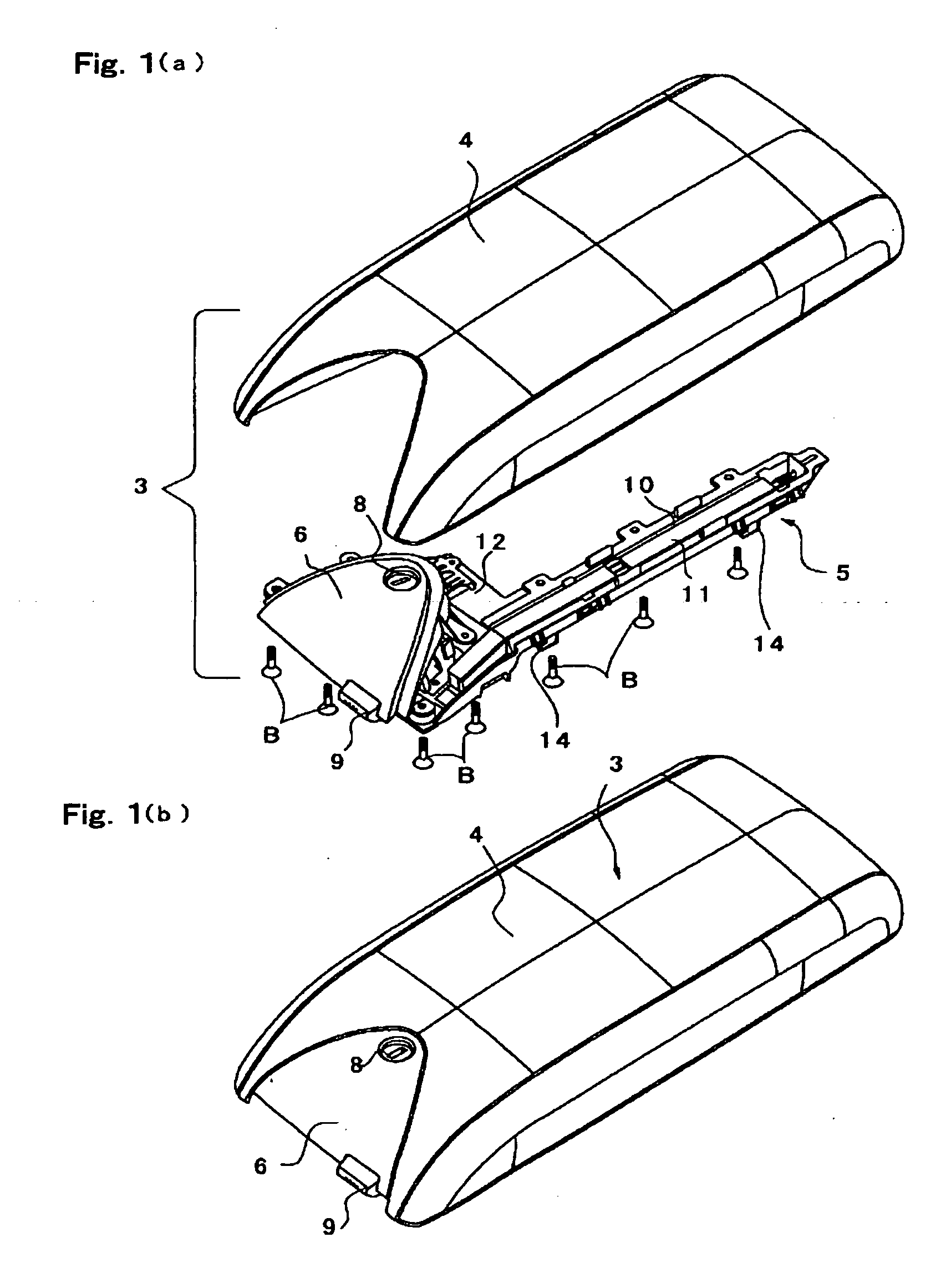
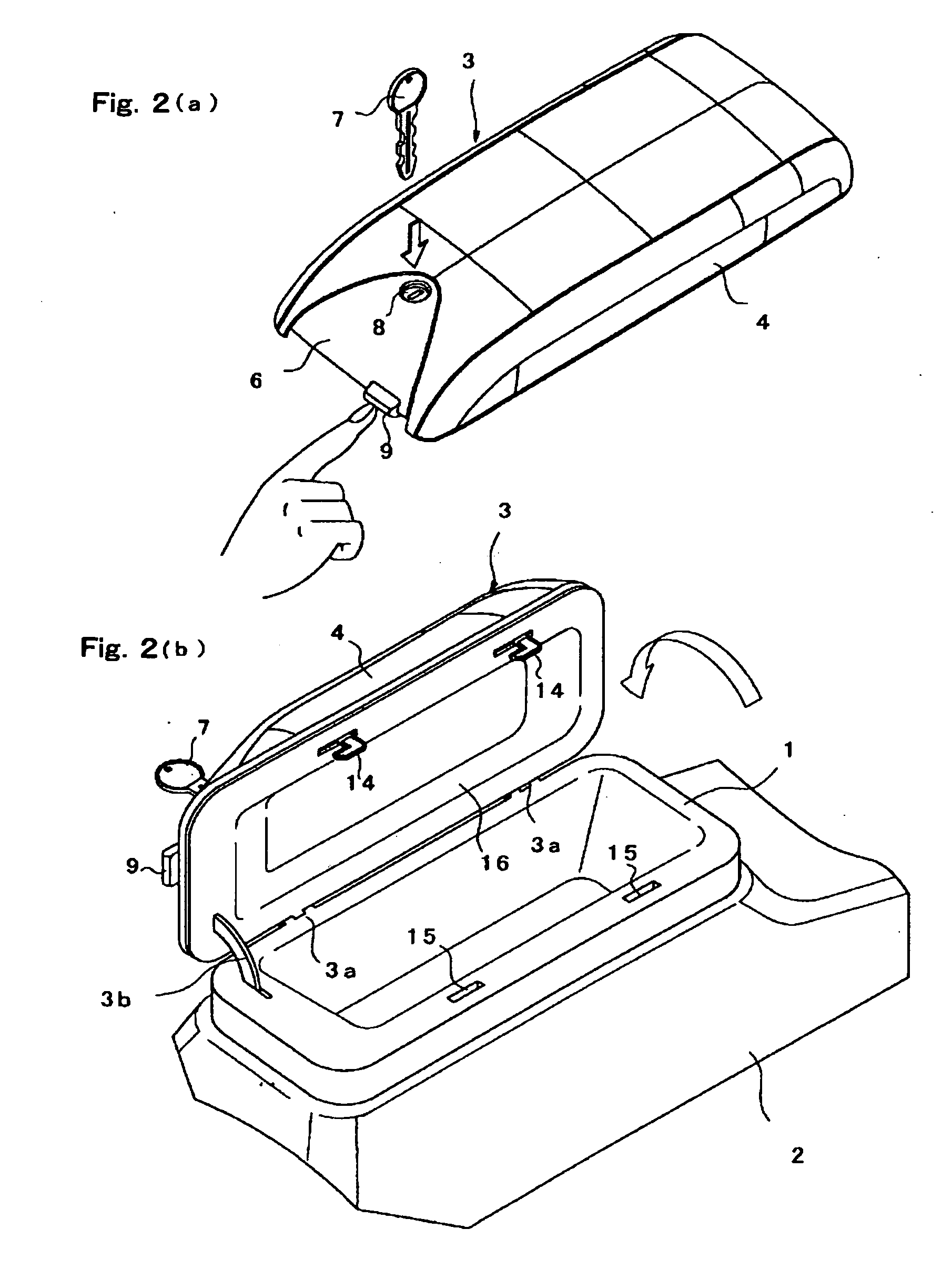
[0028]The lock device according to the present invention is not limited to a specific application as long as the lock is disposed in a lid member so as to be capable of keeping a counterpart of a main body closed. As a specific example, the lock device according to the present invention is preferably applied to a case where, as shown in FIGS. 1(a) and (b), and FIGS. 2(a) and (b), a lid 3 as the lid member is selectively switched from a closed state to an open state and vice versa with respect to a box 1 as the main body, the lid 3 includes a cylinder lock 8 and is configured to close an opening end is of the box 1 and to keep the opening end closed when being locked.

[0029]Specifically, in FIGS. 1(a) and (b), and FIGS. 2(a) and (b), reference numeral 1 designates the console box (hereinbelow, referred to as the box), which is disposed in a proper portion of a center console 2 extending from a middle position of an instrument panel in a right-to-left direction toward a rear direction ...


PUM


Abstract

There is provided a lock device which is adapted to hold a lid member 3 with a lock 8 at a counterpart of a main body 1 in a closed state, which comprises an operating button for an unlocking operation 9; a slidable engagement member 11 having an engageable portion 14, the engageable portion being configured to be selectively brought into engagement with and out of engagement with the main body 1; and a coupling member 20 configured to interlock the operating button 9 and the engagement member 11 with a locking operation and the unlocking operation applied to the lock 8 so that the operating button 9 and the engagement member 11 are set in an interlocked state by the unlocking operation and are set to be free of the interlocked state by the locking operation; whereby the engagement member 11 is slid through the coupling member 20 to bring the engagement member 14 out of engagement with the main body 1 so as to be switched to an open state by operating the operating button 9 when the lock 8 is set in an unlocked position.

Description

TECHNICAL FIELD[0001]The present invention relates to a lock device, which is adapted to lock a lid member with a lock in order to set the lid member in a closed state, more specifically a lock device, which is configured not only to be particularly resistant to unauthorized unlocking actions in a locked position in a sufficient way but also to smoothly perform an opening and closing operation after being unlocked.BACKGROUND ART[0002]As a center console disposed in an automobile, there has been known one wherein a lid member, which covers an upper opening of a center console box in an openable and closable way and is configured to serve as an armrest as well as shown in, e.g. Patent Document 1 listed below. In such a case, it is possible to house a relatively large article, such as a notebook computer, by making use of a feature that the console box has a relatively large volume and a great length in a front-to-rear direction. This type of structure is configured to protect a housed...

Claims


Application Information

Patent Timeline
Patent Type & Authority Applications(United States)
IPC IPC(8): E05B63/22E05B83/30B60R7/04B65D55/14E05B77/44E05B79/22E05B83/32
CPCB60R7/04E05B1/0038E05B13/005E05C9/026E05B83/30E05B83/32E05C1/12Y10T70/554Y10T70/5558Y10T70/7486Y10T70/7819Y10T292/0836Y10T292/0853
Inventor SOMA, TOSHIAKI
Owner NIFCO INC
Learn More